
Manual

Instructions
Publication 500LC–IN005A–EN–P May 2005
Control Module Kits
500LC–47CM*,
500LC–48CM*, 500LC–49SS* for
Bulletin 500LC Lighting Contactors
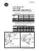
Use these instructions to add optional control modules onto Bulletin 500LC
Lighting Contactors.
Control
Module
2–Wire Control
500LC –47C M*
3–Wire Control
500LC –48C M*
Form 3 Con trol
500LC– 49SS*
M
o
d
u
l
e
Voltage
Kit No.
Kit No. Kit No.
12V AC/DC 500LC–47CM12 500LC–48CM12 500LC–49SS12
24V AC/DC 500LC–47CM24 500LC–48CM24 500LC–49SS24
120V AC 500LC–47CM120 500LC–48CM120 500LC–49SS120
240 / 277V AC 500LC–47CM240 500LC–48CM240 500LC–49SS240
These control modules can be field i nstalled on the bottom or right side
of t he lighting contactor depending o n the number of conta ctor poles.
Each module is suitable only for the control voltage marked on it.
Table A – Ratings for Control Modules
Control
500LC–47CM* 500LC–48CM* 500LC–49SS*
C
o
n
t
r
o
l
Module
AC
DC AC DC AC DC
12V AC/DC 0.60 VA 0.32 W att 0.34 VA 0.36 W att 0.68 VA 0.70 W att
24V AC/DC 0.85 VA 0.36 W att 0.34 VA 0.38 W att 0.70 VA 0.72 W att
120V AC 1.90 VA — 1.60 VA — 3.70 VA —
240 / 277V AC 4.00 VA — 2.50 VA — 6.00 VA —
F igur e 1 Bottom mountin g Figure 2 Side mounting
Use outer holes in
legs for mounting.
Use inner
holes for
mounting.
Control
Module
Control
Module