
INSTALLATION MANUAL Manual

Chapter 7
Installing 1771 I/O
7-10
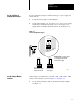
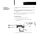
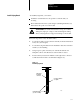
On the 1771-AM1, -AM2 I/O chassis with integral power supply and
adapter set the switches as shown in Figure 7.5.
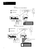
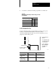
Figure 7.5
Switch
Settings on the I/O Chassis with Integral Power Supply and Adapter
(1771AM1,AM2)
Last State
On
Off
Outputs of this I/O chassis remain in their last state
when a fault is detected by this I/O adapter.
detected by this I/O adapter.
Processor Restart Lockout
On
Off
The I/O chassis can be
restarted from the processor
The processor is locked out
from restarting the I/O
chassis after a fault.
Data Transmission Rate
On
Off
57.6k bit/s (10,000 ft. max.)
115.2k bit/s (5,000 ft. max.)
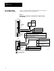
SW1
SW2
Always
On
Always
On
Output of this I/O chassis are turned Off when a fault is
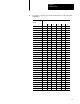
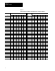
I/O Rack
Number
on
on
off
off
Starting
I/O Group
on
off
on
off
0
2
4
6
Addressing
1/2slotOn
1slot (select this always for 1771AM1)Off
12211I
12345678
Off (away from board)
On (toward board)
9101112 1234 56
Set 1771AM1, AM2 I/O
Chassis/Adapter Switches