
INSTALLATION MANUAL Manual

Chapter 7
Installing 1771 I/O
7-2
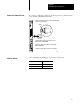
On the 1771-A1B, -A2B, -A3B, -A3B1, -A4B chassis set the backplane
switches to determine:
last state (switch 1)
processor restart lockout (switch 2)
type of addressing (switches 5 and 6)
Set these switches before you install the adapter module.
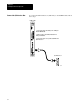
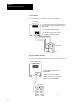
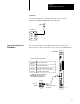
1. Locate the eight switches located on the left side of the
chassis backplane.
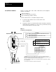
2. Using the worksheet, set the I/O chassis switch assembly as indicated
with a ball-point pen (Figure 7.1). Do not use a pencil because the tip
can break off and jam or short the switch.
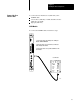
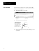
Figure 7.1
Set
Switches on the I/O Chassis
Last State
On
Off
Processor Restart Lockout
On
Off
Addressing
Off Off
On Off
Off On
Always
Always
16191
On
On
On On
2slot
1slot
2
1/2slot
2,
3
Not allowed
Outputs of this I/O chassis remain in their last state when a fault is
detected by this I/O adapter
.
1
Outputs of this I/O chassis are turned off when a fault is
detected by this I/O adapter.
1
A
TTENTION:
If you set this switch to the
ON
position, when a fault is detected, outputs connected to this
chassis remain in their last state to allow machine motion to continue. W
e recommend that you set switch 1 to the
OFF
position to deenergize outputs wired to this chassis when a fault is detected.
2
The 1771AS adapter does not support 1slot or 1/2slot addressing. When you use this adapter
, set switches 5
and 6 to the
OFF
position.
3
The 1771ASB series A adapter does not support 1/2slot addressing.
The I/O chassis can be restarted from
the processor.
The processor is locked out from
restarting the I/O chassis after a fault.
12345678
Off
(away from board)
On (toward board)
Set I/O Chassis Switches