
INSTALLATION MANUAL Manual

Chapter 6
Installing the Vision Components
6-6
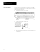
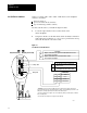
You can connect up to 16 I/O modules to the I/O board (1771-JMB).
Check your vision documentation to see which connections you have to
make and follow the steps below.
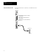
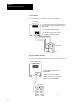
1. Gather the I/O modules you are to install.
0123456789
10
11 12 14
0
15
49
13
11
1
KEY
SLOT
13
2 connectors for
trigger inputs
14 connectors for
general outputs
16899
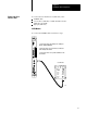
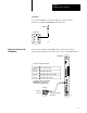
2. Attach each I/O module to the I/O board.
(
1. Push the I/O module into its
connectors (see your system
designer vision information).
2. Using a phillips screwdriver,
secure the connection by
tightening the module's screw.
16900
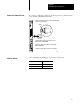
DIMENSIONS
(MILLIMETERS)
INCHES
3. Wire the terminal strip as indicated in your system designer vision
documentation.
Connect the I/O Board