
INSTALLATION MANUAL Manual


Chapter 4
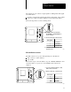
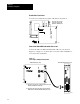
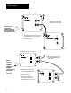
Installing the Modules
4-33
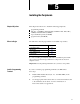
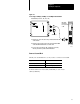
Specify Switch Settings on the OSI Carrierband/Broadband
Interface Module
Switch: Position: Description:
1 up if there is a valid image in nonvolatile memory, the OSI interface module will enter fully operational
mode after:
• a power cycle, regardless of the mode preceding the power cycle
• you enter a reset command from the AB MAP Station Manager, regardless of the mode
preceding the reset
• you enter a change mode to Fully Operational from the AB MAP Station Manager
if there is not a valid image in nonvolatile memory, the OSI interface module will not enter fully
operational mode but will enter Partially Operational mode.
down the OSI interface module will enter partially operational mode after:
• a power cycle, regardless of the mode preceding the power cycle
• you enter a reset command from the AB MAP Station Manager, regardless of the mode
preceding the reset
• you enter a change mode to Partially Operational from the AB MAP Station Manager
2 up the OSI interface module uses user defaults, if available, at powerup or reset (see the PI OSI Interface
Software User's Manual for a list of user defaults). If user defaults aren't available, the interface will
use AB communication defaults.
down the OSI interface module uses AB communication defaults at powerup or reset.
3 preset at AB reserved (do not change)
4 preset at AB reserved (do not change)
Important:
Keep switches 3 and 4 in the up position; otherwise, the PI system stays in a power cycle.