
INSTALLATION MANUAL Manual

Chapter 4
Installing the Modules
4-29
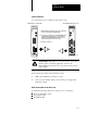
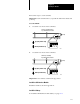
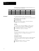
1. Using the pin-outs in the table below, construct a cable depending
upon the type of device you are connecting. The OSI interface
module’s RS-232 port is configured as a DCE port.
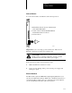
RS232C
Pin: Signal:
1 reserved. The reserved signals are for future use and shouldn't be wired to.
The OSI Interface's RS232 port does not supply a shield connection.
2 TXD
3 RXD
4 reserved
5 signal ground
6 reserved
7 reserved
8 reserved
9 reserved
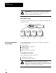
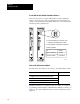
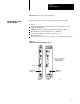
Figure 4.2
Pin
Assignments for the 9Pin RS232 Connector
5
4
3
2
1
9
8
7
6
RS232 port
18394
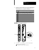
Carrierband
module
Broadband
module
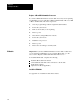
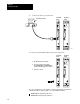
2. If you want to use a shielded RS-232 cable, wire the shield:
at the other end of the cable or
via an RS-232 connector with a metal hood