
INSTALLATION MANUAL Manual

Chapter 4
Installing the Modules
4-16
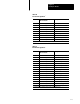
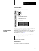
Table 4.E
Configure
T
ermination Resistors for the RS2
If the transmission rate is: And the scanner is physically located: Then put the internal 150Ohm
terminationresistor jumper in the:
57.6k bit/s or 115k bit/s middle of remote I/O link out position
end of remote I/O link in position
230k bit/s middle of remote I/O link out position
end of remote I/O link out position, and attach 82Ohm termination
resistor between pins 2 and 3
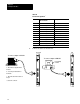
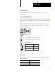
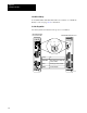
Figure 4.1
RS2
Internal 150Ohm T
ermination Resistors
(Front)
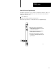
Module
Memory module
RS2 (internal 150Ohm termination resistor)
17085
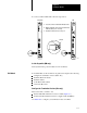
Termination
Resistor
CH JMPR IN OUT
1 E1 3 2 1 3 2 1
2 E2 3 2 1 3 2 1
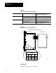
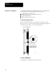
Install the RS
Install the module as shown in appendix A.