
INSTALLATION MANUAL Manual

Chapter 4
Installing the Modules
4-14
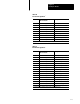
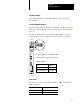
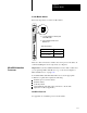
Table 4.D
RS423
Pin Assignments
1
Pin: Input to RM or KA/output from
RM or KA module:
Description:
1 na chassis ground
2 output transmitted data
3 input received data
4 output request to send
5 input clear to send
6 input data set ready
7 na signal ground
8 input received line signal detector
14 not applicable send common
16 na receive common
20 output data terminal ready
1
Compatible
with RS423 standard for the signals used.
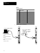
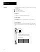
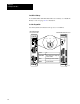
2. Connect the device as shown below.
RM
Programming
terminal
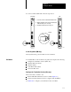
To connect computer to RM CH1:
16748
a. Attach the usersupplied cable to
the device.
b. Locate the port labeled CH1 on
the module.
c. Attach the cable from the device to
the port.
d. Secure the connector.
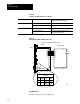
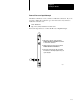
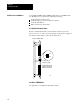
KA module
To connect computer to KA CH1: