
INSTALLATION MANUAL Manual

Chapter 4
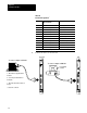
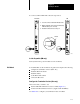
Installing the Modules
4-13
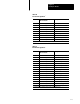
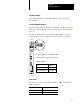
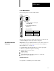
Table 4.B
RS232
Pin Assignments
1
Pin: Input to RM or KA/output from
RM or KA module:
Description:
1 not applicable chassis ground
2 output transmitted data
3 input received data
4 output request to send
5 input clear to send
6 input data set ready
7 na signal ground
8 input received line signal detector
20 output data terminal ready
1
Complies
with the RS232 standard as a DTE typeD interface.
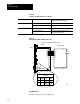
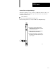
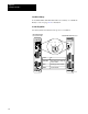
Table 4.C
RS422
Pin Assignments
1
Pin: Input to RM or KA/output from
RM or KA module
Description:
1 na chassis ground
2 output transmitted data
14 output transmitted data
1
3 input received data
16 input received data
1
4 output request to send
19 output request to send
1
5 input clear to send
13 input clear to send
1
6 input data set ready
22 input data set ready
1
7 na signal ground
8 input received line signal detector
10 input received line signal detector
1
20 output data terminal ready
23 output data terminal ready
1
1
Compatible
with RS422 equipment as long as a pointtopoint connection is used.