
INSTALLATION MANUAL Manual
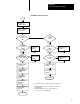

Cable Connections for the RM and KA Module
Appendix C
C-11
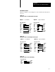
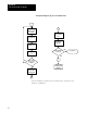
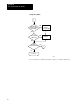
Null Modem Cables
Figure C.9, Figure C.10, and Figure C.11 show null-modem cable pinouts
for port 1.
Figure C.9
NullModem
Cables for FullDuplex Modem Option
GND
SHIELD
TxD
1
2
3
4
5
6
7
RxD
RTS
CTS
DSR
SIGNAL
DCD
SIGNAL
RTS
GND
DCD
DTR
SHIELD
RxD
TxD
CTS
DSR
8
20
DTR
SHIELD
TxD
1
2
3
4
5
6
8
RxD
RTS
CTS
DSR
DCD
RTS
DCD
DTR
SIGNAL
SHIELD
RxD
TxD
SIGNAL
20
7
DSR
DTR
GND GND
CTS
RM or KA module RM or KA module
Option 1 Option 2
uses DSR/DTR bypasses DSR/DTR
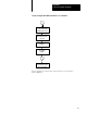
Figure C.10
NullModem Cables for HalfDuplex Modem Option
GND
SHIELD
TxD
1
2
3
4
5
6
7
RxD
RTS
CTS
DSR
SIGNAL
DCD
SIGNAL
RTS
GND
DCD
DTR
SHIELD
RXD
TXD
CTS
DSR
8
20
DTR
SHIELD
TxD
1
2
3
4
5
7
8
RxD
RTS
CTS
SIGNAL
DCD
DCD
RTS
DSR
DTR
SHIELD
RxD
TxD
CTS
DSR
6
20
SIGNAL
GND
GND
DTR
Option 1 Option 2
RM or KA module RM or KA module
uses DSR/DTR bypasses DSR/DTR
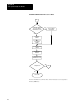
Figure C.11
NullModem Cables for No Handshaking
GND
SHIELD
TxD
1
2
3
7
RxD
SIGNAL SIGNAL
GND
SHIELD
RxD
TxD
RM or KA module