
INSTALLATION MANUAL Manual
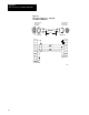
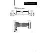
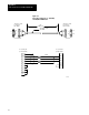

Cable Connections for the RM and KA Module
Appendix C
C-2
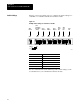
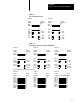
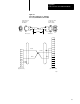
Figure C.1 shows an example of how to configure the switch settings for a
1770-KF2 or a 1785-KE communication interface module.
Figure C.1
Example
switch settings for 1770KF2 or 1785KE
SW5
57600
bit/s
SW6
9600
bit/s
SW7
DH+
SW8
RS232
SW2
Address
SW3
Address
SW4
Address
SW1
Full duplex
BCC None
(Parity)
SW8 SW1 SW2 SW3 SW4 SW5 SW6 SW7
Off
(0)
On
(1)
Side view
17091
Switch: Function:
SW1 asynchronous link features
SW2, SW3, SW4 station address
SW5 DH baud rate
SW6 asynchronous link baud rate
SW7 DH+ network
SW8 RS232C or RS422 selection
For more information about the different possible switch settings, see the
documentation for your communication interface module.
Switch Settings