
INSTALLATION MANUAL Manual

Chapter 1
Preparing for Installation
1-3
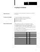
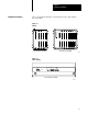
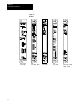
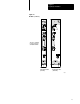
After you unpack the hardware, use the figures below to help identify
the components.
Figure 1.1
Chassis
4slot chassis (5110A4/B) 8slot chassis (5110A8/B)
19775
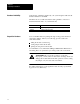
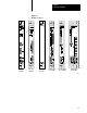
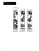
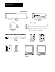
Figure 1.2
Fan
Assembly
Fan assembly (5110FAN8)
16725
Fan
Status
Cable
100/200
V
ac
220
Vac
Fan Status
Gnd L2/N L1
Fuse
15A 250V
Slow Blow
Identify the Hardware