
INSTALLATION MANUAL Manual

Chapter 11
Checking the Hardware
11-8
4. To make sure you have wired each I/O correctly, perform a continuity
test for each I/O wired.
To test the vision components, follow the steps below:
1. Apply power to each vision device and make sure the PASS/FAIL
indicators are GREEN.
If the indicators are not green:
remove power
make sure the connections are correct and secure
re-apply power and re-check indicators
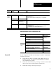
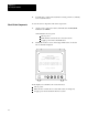
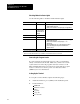
2. Check the monitor’s screen. A message similar to the one shown
below should be displayed.
ALLEN-BRADLEY
Configurable Vision Input Module
Bulletin 5370-CVIM
Series xxx Revision X
Copyright 1993 Allen-Bradley Company
Phase I Diagnostics Completed Status = OK
Phase II Diagnostics Completed Status = OK
System Initialization Completed Status = OK
Power-up Completed
17214
If the display is not similar to the one shown above:
remove power
make sure the connections are correct and secure (see chapter 6)
re-apply power and re-check the monitor’s screen
Check
V
ision Components