
INSTALLATION MANUAL Manual

Chapter 11
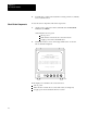
Checking the Hardware
11-7
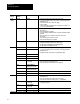
If you
have a:
If it is not:
It should be:Check the LED
labeled:
1
MEM
ERR will be on at initial power up until memory is cleared or downloaded.
2
These LEDs light after INTERCHANGE software has been loaded.
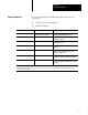
Ethernet
Interface
module
PASS/FAIL GREEN
• cycle power by turning off the power from the power supply and then
turning it back on.
• make sure the module is seated properly see appendix A.
BACKPLANE OFF
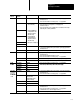
3
ENET Flashing GREEN or of
f (If
connected and
communicating on the
Ethernet network)
make sure the connection to the Ethernet network is secure.
ERROR CODE OFF
• cycle power by turning off the power from the power supply and then
turning it back on.
• make sure the module is seated properly see appendix A.
• it will blink the error code. Call support services.
3
This
LED lights after Network INTERCHANGE software has been loaded.
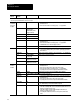
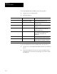
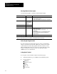
RM or KA Module on the Communication Link
Channel: With this protocol: LED should be:
CH 1 Master Flashing GREEN
(when communication
Slave
(when communication
is occurring)
DF 1 (if another device is sending you messages and
you are replying)
DF 1 (If no other device is sending you messages) OFF
Inactive OFF
CH 2 and DH link (and there's no other activity on the network) GREEN
CH 3 DH link (and no messages are being sent to you on
the network)
OFF
DH link (and you are replying to messages from
another device on the network)
Flashing GREEN
Inactive OFF
DH+ link Flashing GREEN
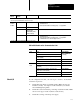
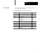
If your configuration has I/O, your next step is to check it. To check I/O,
follow the steps below.
1. Check the keying bands of each I/O module. Make sure they are
installed correctly. See chapter 7 in this manual if you’re unsure
about installing keying bands.
2. Check the location and chassis positioning of each I/O module. Make
sure it is in its proper location (chassis, rack, and slot).
3. Check the ac wiring on the I/O power supply.
Check
I/O