
INSTALLATION MANUAL Manual

Chapter 9
Connecting the I/O Link
9-9
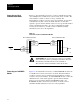
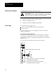
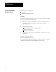
Figure 9.8
Connections
to RediP
ANEL Module
Bulletin 2705
RediPANEL Module
Blue
Shield
Clear
Blue
Shield
Clear
Blue
Shield
Clear
Bulletin 2705
RediPANEL Module
To
Scanner
150
Ω
16511
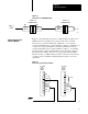
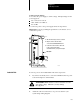
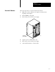
Figure 9.9 shows I/O link connections to a PLC interface module (cat. no.
3500-NA1) both as a middle device and as an end device on a link.
Connection is to the X4 terminal strip. Terminals 1, 2, 9, and 10 are
connected internally for line 1 (blue-insulation conductor). Terminals 3, 4,
7, and 8 are connected internally for the shield. Terminals 5 and 6 are
connected internally for line 2 (clear-insulated conductor). At each PLC
interface module, connect the shield drain wire of each cable segment to
give the shield continuity. However, never ground the shield at a PLC
interface module. At a PLC interface module connected as an end device
on a link, connect a 150-Ohm 1/4-Watt termination resistor across the
signal lines.
Figure 9.9
Connections
to PLC Interface Module
3500-NA1
PLC
Interface
Module
X4
1
2
3
4
5
6
7
8
9
10
Blue
Shield
Clear
Clear
Shield
Blue
X4
1
2
3
4
5
6
7
8
9
10
Clear
Shield
Blue
To
Scanner
3500-NA1
PLC
Interface
Module
150
Ω
16512
Connecting to a PLC
Interface Module