
INSTALLATION MANUAL Manual

Chapter 9
Connecting the I/O Link
9-6
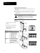
Make ExtendedLocal I/O Connections
Important: Follow these considerations when making extended-local
I/O connections:
do not apply power to an I/O rack containing a extended-local I/O
adapter module until all extended-local I/O cables are installed
and connected
make extended-local I/O connections according to Figure 9.4
ATTENTION: Turn off power to the extended-local I/O
adapter module before connecting or disconnecting
extended-local I/O cables to prevent the possibility of
corrupting the data.
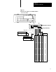
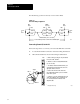
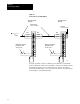
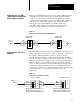
Figure 9.4
Make
ExtendedLocal I/O Connections
18586
1. Connect the singleend connector to channel 5
of the RS5.
2. Route the cable to the first local I/O and adapter.
3. Connect the dualend connector to the local
I/O adapter module. Be sure to screwin the
retaining screws tightly.
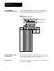
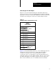
If the adapter: Then:
is not the last one
on the link
is the last one on
the link
1. Connect the singleend of a
local I/O network cable to the
exposed end connector on the
adapter module. Press and
hold the clips and snap to the
mating connector.
2. Route the cable to the next
adapter and connect the
dualend connector to it.
Terminate the link by installing the
local I/O terminator (1771CXT) to
the exposed end of the dualend
connector on the last adapter
module. The system will not run
without it. The terminator is included
with the processor.
RS5 module
4.