
INSTALLATION MANUAL Manual

Chapter 9
Connecting the I/O Link
9-3
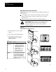
Connecting to 1771ASB Adapter
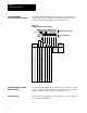
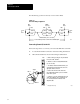
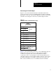
Figure 9.2 shows the terminal identification label which indicates the
proper connections for each 1771-ASB I/O adapter module in an I/O link.
This label is on the side of the module. Make the connections at the screw
terminals on the wiring arm on the front of each I/O adapter module.
Figure 9.2
I/O
Adapter Module T
erminal Identification Label
Terminal
Identification
Cat. No. 1771-ASB
1 Line 1
Shield
Line 2
No connection
No connection
No connection
No connection
No connection
No connection
No connection
2
3
4
5
6
7
8
9
10
11
12
IN
RET
Reset
Cable
10910
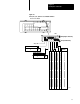
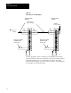
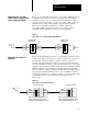
Figure 9.3 shows an I/O link connections to a 1771-ASB adapter both as a
middle device and as an end device on a link. The blue-insulation
conductor corresponds to line 1. The clear-insulation conductor
corresponds to line 2. At each adapter, connect the shield drain wire of
each cable segment to give the shield continuity. However, never ground
the shield at an adapter. At an adapter connected as an end device on a
link, connect a terminator (cat. no. 1770-XT) between the terminals.