
INSTALLATION MANUAL Manual

Chapter 9
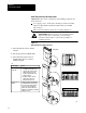
Connecting the I/O Link
9-2
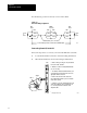
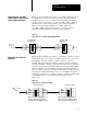
For RS, always ground one and only one end of the shield.
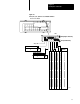
Figure 9.1
General
Cabling Configuration
End
device
End
device
Middle
device(s)
Blue
Shield
Clear
Blue
Shield
Clear
Blue
Shield
Clear
Blue
Shield
Clear
Twinaxial cable (cat. no. 1770CD)
See the table in previous section for the maximum length.
150 Ω
or
82 Ω
150 Ω
or
82 Ω
16507
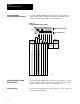
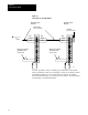
Connecting Remote I/O to the RS
Follow the steps below to connect your remote I/O link cable to the RS.
1. Locate the I/O channel connection on the I/O wiring information.
2. Wire the I/O channel as shown in the wiring documentation.
Blue 1
Shield
Clear 2
RS5
19789
a. Remove the male connectors for ports labeled
CH 1, CH 2, CH3
1
and CH4
1
.
b. Wire these connectors using Twinaxial Cable
(cat. no. 1770CD).
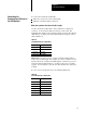
c. According to the I/O documentation from your
system designer, attach wired connectors to the
appropriate female connectors.
d. Connect the other end of the cable to the
remote I/O adapter module or processor module
in the remote system.
e. If there ia a 1771AS, ASB module at the end
of the remote I/O link, connect a terminator (cat.
no. 1770XT) between the terminals on the
adapter module.
1
This applies to RS5 only
.