
INSTALLATION MANUAL Manual

Chapter
9
9-1
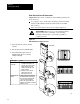
Connecting the I/O Link
This chapter describes how to connect an I/O chassis to the RS.
The Medium
In an I/O link, the RS and the I/O adapters communicate with one another
through 1770-CD twinaxial cable which provides a physical bus medium.
You can use the twinaxial cable to form the bus connection between them
in either a daisy-chain or a trunkline/dropline configuration. This chapter
describes how to connect a daisy-chain configuration. See publication
1770-6.2.1 for information on how to construct a
trunkline/dropline configuration.
For each I/O link of the scanner module, you can individually select to
have a data-transmission rate of 57.6k bit/s, 115.2k bit/s, or 230k bit/s. At
each I/O adapter, you must select the same rate as you select for the link at
the RS.
A higher transmission rate provides a faster I/O update. However, the
higher the rate of transmission, the shorter the maximum cable length.
If the data transmission rate is: Then the maximum cable length is:
57.6k bit/s 10,000 ft.
115.2k bit/s 5,000 ft.
230.4k bit/s 2,500 ft.
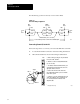
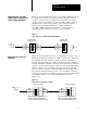
Cabling Configuration
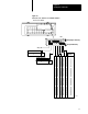
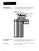
A general cabling configuration is shown in Figure 9.1. The cable has a
signal conductor with blue insulation, a signal conductor with clear
insulation, and a bare shield drain wire. Observe the color code
convention used in the following figures to provide the proper signal
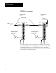
polarity. At each end device, connect a termination resistor.
For a transmission rate of: Connect an:
57.6k bit/s 150Ohm termination resistor
115.2k bit/s 150Ohm termination resistor
230.4k bit/s 82Ohm termination resistor
Chapter Objectives
Connecting the Remote
I/O Link