
INSTALLATION MANUAL Manual

Chapter 8
Installing Nonstandard I/O
8-6
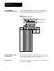
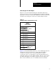
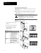
To install a 2705 RediPANEL push-button module, set the switches of
switch assembly SW2 as described in publication 2705-800. Set the
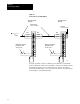
switches of switch assembly SW1 as shown in Figure 8.4.
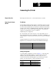
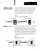
Figure 8.4
Setting
RediP
ANEL Module Switches
0
1
2
3
4
5
6
7
10
11
12
13
14
15
16
17
on
on
on
on
on
on
on
on
off
off
off
off
off
off
off
off
12214I
on
off
on
off
on
off
on
off
on
off
on
off
on
off
on
off
on
on
off
off
on
on
off
off
on
on
off
off
on
on
off
off
on
on
on
on
off
off
off
off
on
on
on
on
off
off
off
off
I/O Rack
Number
on
on
off
off
Starting
I/O Group
on
off
on
off
0
2
4
6
20
21
22
23
24
25
26
27
30
31
32
33
34
35
36
37
on
on
on
on
on
on
on
on
off
off
off
off
off
off
off
off
on
off
on
off
on
off
on
off
on
off
on
off
on
off
on
off
on
on
off
off
on
on
off
off
on
on
off
off
on
on
off
off
on
on
on
on
off
off
off
off
on
on
on
on
off
off
off
off
on
on
on
on
on
on
on
on
on
on
on
on
on
on
on
on
on
on
on
on
on
on
on
on
on
on
on
on
on
on
on
on
on
on
on
on
on
on
on
on
on
on
on
on
on
on
on
on
off
off
off
off
off
off
off
off
off
off
off
off
off
off
off
off
SW1
12345678
Off (away from board)
On (toward board)
To install a 2705 RediPANEL keypad module, set the switches of switch
assemblies SW2 and SW3 as described in publication 2705-801. Set the
switches of switch assembly SW1 as shown in Figure 8.4.
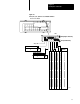
After you finish installing all of your I/O modules, proceed to chapter 9 to
connect the I/O link cabling.
Setting RediPANEL
Pushbutton Module Switches
Setting RediPANEL Keypad
Module Switches
What to do Next