
INSTALLATION MANUAL Manual

Chapter 8
Installing Nonstandard I/O
8-4
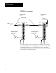
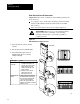
To install a 1785 PLC-5 processor in adapter mode, set the switches in
switch assembly SW2 as described here; set all other switches, including
the I/O chassis backplane switches as described in the 1785 PLC-5
Installation Manual (1785-6.6.1).
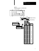
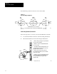
Use switch assembly SW2 to set the I/O rack number and the number of
words to communicate. These switches are accessible from the bottom of
the module. Always set switch 1 to up (Figure 8.3).
Number
of W
ords
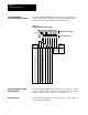
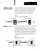
Switch 2 determines the number of 16-bit words the scanner will write to
the PLC-5 processor and the number of words read from the PLC-5
processor. Set switch 2 as follows:
If switch 2 is set as: Then the scanner writes and reads:
down four words to and from the PLC5 processor.
up eight words to and from the PLC5 processor.
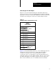
I/O Rack Number
When a 1785 PLC-5 processor is used as an I/O adapter for the PLC-5/250
RS, it must be assigned an I/O rack number through which it is addressed
from the scanner. Switches 4 through 8 determine the I/O rack number
through which the 1785 PLC-5 controller is addressed by the scanner.
Starting I/O Number
Switch 3 determines the starting I/O group number. If the number of
words is 8, the starting I/O group must be number 0.
Setting
1785 PLC5
Processor Switches