
INSTALLATION MANUAL Manual

Chapter 8
Installing Nonstandard I/O
8-3
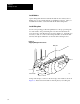
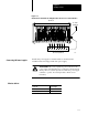
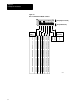
To install a PLC interface module (3500-NA1), set the switches as
described here; set the jumpers as described in publication 1352-5.0.2.
Switch assemblies SW3, SW6, and SW7 are located across the bottom of
the module (Figure 8.2).
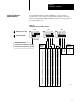
Figure 8.2
Setting
PLC Interface Module Switches
SW3 SW6 SW7
12213I
0
1
2
3
4
5
6
7
10
11
12
13
14
15
16
17
on
on
on
on
on
on
on
on
off
off
off
off
off
off
off
off
on
off
on
off
on
off
on
off
on
off
on
off
on
off
on
off
on
on
off
off
on
on
off
off
on
on
off
off
on
on
off
off
on
on
on
on
off
off
off
off
on
on
on
on
off
off
off
off
I/O Rack
Number
on
on
off
off
Starting
I/O Group
on
off
on
off
0
2
4
6
20
21
22
23
24
25
26
27
30
31
32
33
34
35
36
37
on
on
on
on
on
on
on
on
off
off
off
off
off
off
off
off
on
off
on
off
on
off
on
off
on
off
on
off
on
off
on
off
on
on
off
off
on
on
off
off
on
on
off
off
on
on
off
off
on
on
on
on
off
off
off
off
on
on
on
on
off
off
off
off
on
on
on
on
on
on
on
on
on
on
on
on
on
on
on
on
on
on
on
on
on
on
on
on
on
on
on
on
on
on
on
on
on
on
on
on
on
on
on
on
on
on
on
on
on
on
on
on
off
off
off
off
off
off
off
off
off
off
off
off
off
off
off
off
Always Off
Data Transmission Rate
On
Off
57.6k bits/s (10,000 cableft max.)
115.2k bits/s (5,000 cableft max.)
1234
Off
(away from board)
On (toward board)
1234 1234
Setting PLC Interface
Module Switches