Pyramid Integrator Installation Manual
Important User Information Because of the variety of uses for the products described in this publication, those responsible for the application and use of this control equipment must satisfy themselves that all necessary steps have been taken to assure that each application and use meets all performance and safety requirements, including any applicable laws, regulations, codes and standards.
Summary of Changes Summary of Changes Additional Information In general, we improved the format and added greater detail to this manual.
Table of Contents Summary of Changes . . . . . . . . . . . . . . . . . . . . . . . . . . . . i Additional Information . . . . . . . . . . . . . . . . . . . . . . . . . . . . . . . . . i Using this Manual . . . . . . . . . . . . . . . . . . . . . . . . . . . . . . . iii Manual Objectives . . . . . . . . . . . . . . . . . . . . . . . . . . . . . . . . . . . Pyramid Integrator Documentation . . . . . . . . . . . . . . . . . . . . . . . . Who Should Use this Manual . . . . . . . . . . . . . . . . . . .
ii Table of Contents Grounding the Components . . . . . . . . . . . . . . . . . . . . . . . 3 1 Chapter Objectives . . . . . . . . . . . . . . . . . . . . . . . . . . . . . . . . . . . To Ground the Components . . . . . . . . . . . . . . . . . . . . . . . . . . . . Gather the Grounding Documentation . . . . . . . . . . . . . . . . . . . . . Gather the Necessary Tools and Supplies . . . . . . . . . . . . . . . . . . Ground the Components . . . . . . . . . . . . . . . . . . . . . . . . . . . . . . .
Table of Contents iii Installing 1771 I/O . . . . . . . . . . . . . . . . . . . . . . . . . . . . . . . 7 1 Chapter Objectives . . . . . . . . . . . . . . . . . . . . . . . . . . . . . . . . . . . What You Should Have Completed . . . . . . . . . . . . . . . . . . . . . . . Before You Begin . . . . . . . . . . . . . . . . . . . . . . . . . . . . . . . . . . . . Set I/O Chassis Switches . . . . . . . . . . . . . . . . . . . . . . . . . . . . . . Set the I/O Chassis Configuration Jumper . . . . . . . . . .
iv Table of Contents Connecting ac Power . . . . . . . . . . . . . . . . . . . . . . . . . . . . . 10 1 Chapter Objectives . . . . . . . . . . . . . . . . . . . . . . . . . . . . . . . . . . . What You Will Be Doing . . . . . . . . . . . . . . . . . . . . . . . . . . . . . . . Gather ac Wiring Documentation . . . . . . . . . . . . . . . . . . . . . . . Disable Inputs and Outputs . . . . . . . . . . . . . . . . . . . . . . . . . . . . . Power Supply . . . . . . . . . . . . . . . . . . . . . . . . . . . .
Table of Contents v Cable Connections for the RM and KA Module . . . . . . . . . . C 1 What's in this Appendix . . . . . . . . . . . . . . . . . . . . . . . . . . . . . . . . Switch Settings . . . . . . . . . . . . . . . . . . . . . . . . . . . . . . . . . . . . . Cable Connections . . . . . . . . . . . . . . . . . . . . . . . . . . . . . . . . . . . Cable Pinouts . . . . . . . . . . . . . . . . . . . . . . . . . . . . . . . . . . . . . . C 1 C 2 C 3 C 4 Start Up and Configure the Modules . . . . . .
Preface Using this Manual Manual Objectives Read this manual to learn how to install the Pyramid Integrator hardware. Pyramid Integrator Documentation Use this manual with the Pyramid Integrator Design Manual (5000-6.2.10). We assume that you are familiar with: basic cabling wiring grounding procedures programmable controllers For more information, see the Programmable Controller Wiring and Grounding Guidelines (1770-4.1).
Preface Using this Manual Who Should Use this Manual iv Use this manual if you are installing any of the following hardware: Modules: Cat. no.
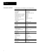
Preface Using this Manual Related Publications For additional information on topics related to the PI system, see these publications: Publication: Catalog No. / Publication No.: Allen Bradley Data Highway Cable Layout Manual 1770 6.2.1 Pyramid Integrator System Design Manual 5000 6.2.
Preface Using this Manual When we refer to words of memory in PI modules, we mean 16-bit words unless otherwise stated. In addition, you may encounter words in different typefaces. We use these conventions to help differentiate descriptive information from information that you enter while programming your PI system. Words or commands that you enter appear in boldface.
Chapter 1 Preparing for Installation Chapter Objectives This chapter lists the tasks that must be completed before you install the hardware. To Prepare for Installation To prepare for installation, complete the following: gather the documentation from your system designer make sure the hardware is available unpack the hardware identify the hardware Gather the Documentation While designing your system, your system designer completes documentation that describes what to install and how.
Chapter 1 Preparing for Installation Hardware Availability Using the list of hardware supplied by your system designer, make sure all the listed hardware is available. Check the invoice to make sure that the catalog numbers on the boxes match the hardware that’s on your hardware list. Unpack the Hardware If the hardware is: Then: not available check with your system designer to see if something has changed. available continue to the next section.
Chapter 1 Preparing for Installation Identify the Hardware After you unpack the hardware, use the figures below to help identify the components. Figure 1.1 Chassis 4 slot chassis (5110 A4/B) 8 slot chassis (5110 A8/B) 19775 Figure 1.
Chapter 1 Preparing for Installation Figure 1.
Chapter 1 Preparing for Installation Figure 1.
Chapter 1 Preparing for Installation Figure 1.
Chapter 1 Preparing for Installation Figure 1.6 Modules (continued) The cat. no. 5820 CC is used on an 802.
Chapter 1 Preparing for Installation Figure 1.
Chapter 1 Preparing for Installation Figure 1.8 Industrial Disk 159 / 209, 418, or 480 Mbyte industrial disk (5730 ID3 / 5710 ID4, ID5, ID6, ID7) 18541 Figure 1.9 4 Port Distribution Panel 4 port distribution panel (5710 DPI) 17186 Figure 1.
Chapter 1 Preparing for Installation Module Weights What to do Next 1-10 Here are the weights of the PI modules, the fan assembly, industrial disks, and the 4- and 8-slot chassis: Module: Pounds: Kilograms: RM 4 lbs, 4.0 oz 1.92 kg LP 3 lbs, 13.5 oz 1.74 kg RS2 3 lbs, 11.0 oz 1.67 kg RS5 2 lbs, 15.6 oz 1.35 kg MicroVAX Information Processor EP 8 lbs, 6.5 oz 3.81 kg MicroVAX Information Processor EE 8 lbs, 6.5 oz 3.81 kg MicroVAX Information Processor 9 lbs, 6.0 oz 4.
Chapter 2 Mounting the Components Chapter Objectives Read this chapter to learn how to mount various system components.
Chapter 2 Mounting the Components Gather the Tools and Supplies Gather these tools and supplies you will need: #10-32 screws, lock washers, flat washers and screw driver set, if you are rack mounting #10-32 screws, lock washers, flat washers, and drill and tapping equipment if you are panel mounting wrench set, if applicable wire brush tape measure marker or grease pencil copper ground bus two spacers, for use between the ground bus and panel Rack Mount the Components To: Then: Panel mount the compone
Chapter 2 Mounting the Components 2. Prepare the rack. Mark the position of each component you will mount. Make sure the holes line up with the holes of the mounting brackets. Planned position of component on rack #10 32 Nominal hole size 3. 13220 Mount a copper ground bus on the rack: a. Drill two clearance holes for #10-32 mounting screws in the bus. Drill and tap a #10-32 hole for each component you will attach to the rack.
Chapter 2 Mounting the Components c. Attach the ground bus to the rack using the two drilled mounting holes. One connection is shown below. Star washer Rack Copper ground bus #10 32 screw Star washer 4. 13235 Repeat this procedure for each component you mount: a. Position the component on the spot you have prepared for it on the rack. b. Attach the component using #10-32 screws and lock washers. Do not tighten the screws yet (you will tighten the screws after you ground the components).
Chapter 2 Mounting the Components Panel Mount the Components With the equipment, mounting documentation, and tools you are ready to mount the components. Follow these steps to panel mount the components. 1. Prepare the panel: a. Remove the panel from its enclosure and lay the panel flat, with its front facing up. b. Using the mounting worksheet from your system designer, mark the location of the component on the panel for each component you will mount.
Chapter 2 Mounting the Components 2. Prepare to attach the component to the panel: drill and tap a #10-32 hole through the panel at each point where component will attach. 3. Mount a copper ground bus on the panel: a. Drill two clearance holes for #10-32 inch mounting screws in the bus. Drill and tap a #10-32 hole for each component you will mount on the panel. Drilled clearance holes for mounting Drilled and tapped holes 13234 b.
Chapter 2 Mounting the Components 4. Return the panel to its enclosure: a. Scrape paint and other nonconductive finishes from the shoulder studs on the back wall of the enclosure. Scrape clear an area at least as large as the washer to be used. b. Attach the panel to the back wall of the enclosure as shown here: Back wall of enclosure Panel Nut Shoulder bolt on back wall of enclosure Star washer 5. 13871 Repeat this procedure for each component you mount: a.
Chapter 2 Mounting the Components Mount the Fan Assembly To mount the fan assembly, follow the steps below: 1. Remove the four screws in the bottom of the 8-slot chassis with a phillips screwdriver. 16733 2. Remove the fan drawer and air filter from the fan cover. a. Loosen the two screws on the fan drawer and slide the fan from the cover. b. Loosen the two screws on bottom of the drawer and slide the air filter from the fan cover.
Chapter 2 Mounting the Components 3. Attach the fan cover to the bottom of chassis: a. Place the fan cover under the chassis. Make sure the screw holes line up. b. Place the four screws into the holes and tighten them. 19781 4. Install the fan drawer: a. Slide the fan drawer into the fan cover. Make sure the fan drawer engages the rear edge of the fan cover. b. Tighten the two captive screws.
Chapter 2 Mounting the Components 5. Install the filter: a. Make sure the air flow arrows on the front of the filter are pointing up. b. Align the filter with the two clips at the bottom of assembly and slide filter into the assembly. 19783 Mount the Camera To mount a camera, follow the steps below. 1. Mount the camera on your own mounting bracket. a.
Chapter 2 Mounting the Components Mounting a Black and White Monitor (2801 N6, N9, N20) Mounting the I/O Board 1771 JMB Check the mounting documentation to see how you should mount the black and white monitor. If mounting: Make sure: on a table or shelf • the connectors are accessible so you can connect the cables to the monitor • the table or shelf can hold the weight of the monitor place the monitor in the position indicated by the mounting documentation.
Chapter 2 Mounting the Components Attach the User Interface Box To attach the user interface box, follow the steps below: 1. Align the flange of the user interface with the two standoffs on the bottom of the I/O board. POWER 9 10 11 12 13 14 15 BLUE LIGHT PEN GREEN SYNC RED INPUT 16906 2. What to do Next 2-12 Secure the user interface and I/O board to the mounting surface using two screws. After you have mounted the components, go to chapter 3 to ground the system.
Chapter 3 Grounding the Components Chapter Objectives Read this chapter to learn how to ground the components. To Ground the Components To ground the components, complete the following: gather the grounding documentation from your system designer gather the necessary tools and supplies ground the components Gather the Grounding Documentation Gather and check the grounding documentation to locate the point of each component that you are to ground.
Chapter 3 Grounding the Components Ground the Components Follow the grounding documentation and the steps below to ground the components. 1. Prepare and connect grounding conductors to the components. a. Determine which mounting point on the chassis you are going to use to ground the components (some chassis have grounding lugs; for other chassis, you have to use a mounting screw). b. Construct an equipment-grounding conductor for each component.
Chapter 3 Grounding the Components 2. Prepare and connect grounding conductors to the ground bus: a. Construct an equipment-grounding conductor long enough to extend from the ground bus to an enclosure wall. Use 8 AWG stranded wire or equivalent tinned braided cable copper wire (the exact AWG should be in the grounding documentation from the system designer) and ring terminals. b.
Chapter 3 Grounding the Components Important: Make sure the scraped surface of the enclosure wall is in contact with the total surface area of the ring terminal. Enclosure wall Scrape paint Bolt Ground lug Nut Scrape paint on enclosure wall and use a star washer. Star washer c. Equipment grounding conductor 10020 Connect the grounding electrode conductor to your grounding electrode system (earth ground potential). We recommend a direct earth ground for maximum protection.
Chapter 4 Installing the Modules Chapter Objectives This chapter shows you how to install each module and is divided into sections that cover the installation tasks for each module. How to Use this Chapter Use this chapter with the completed module worksheets from the PI Design Manual (5000-6.2.1) to perform various installation tasks for each module. The worksheets contain specific settings and connections for each module. This chapter describes how to make those settings and connections.
Chapter 4 Installing the Modules Disposing of a Lithium Battery ATTENTION: Do not incinerate or dispose of lithium batteries in general trash collection. Explosion or violent rupture is possible. Follow these guidelines when you dispose of the module’s battery. Important: Check your state and local regulations that deal with the disposal of lithium batteries.
Chapter 4 Installing the Modules Emergencies Emergencies can occur due to the battery’s makeup. Major components of the cell are: And these components are: lithium metal highly reactive in water, flammable, and can create toxic fumes when burned. inorganic electrolyte thionyl chloride (SOCI2) fast evaporating, corrosive, has a pungent odor, reacts violently to water, causes burns on contact, and produces toxic and corrosive fumes and chemicals upon decomposition.
Chapter 4 Installing the Modules Leaking Battery If the hermetic seal of the case is broken, ventilate the area. Using tongs, scoop, or shovel, remove the leaking battery to a well-ventilated fire-protected area. Fire ATTENTION: Do not use water or carbon dioxide (CO2) fire extinguishers on the fire. Lithium is reactive with these substances. As described for overheated batteries, explosion or violent rupture is possible. If a cell is ruptured, the exposed lithium is combustible and is reactive in water.
Chapter 4 Installing the Modules ATTENTION: If you have any empty slots in the chassis, install filler plates (5110-FP) in them. Otherwise, the modules could be damaged. To install filler plates, see appendix A. Many of the connections you make to the modules are made to connectors that you wire. If you do not know how to wire these connectors, see appendix A. Important: Save the packing material in case you have to ship a module.
Chapter 4 Installing the Modules Connect the Fan Assembly/External Power Source If you have a fan assembly or are connecting the power supply to an external power source, make this connection. If you don’t have to make this connection, go to the next section. To make this connection, follow the steps below. 1. Determine which fan assembly and/or power source connections you are making.
Chapter 4 Installing the Modules 3. Connect the 5120-CP2 cable to the fan chassis, the power supply and a 24V external power supply. a. Connect the spade lugs to an external 24V power supply. Connect triple red to +. 5120 CP2 b. Connect the right angle connector of the 5120 CP2 cable to the port labeled FAN CHASSIS on the power supply. c. Route the cable away from the Interlock Relay and Line Voltage connectors. Connect triple black to -. Connect single red to + sense or +. d.
Chapter 4 Installing the Modules RM/KA Module To install the RM/KA module, use the worksheets as guides and complete the following: set the RM/KA module switches and jumpers install the module in the chassis install the battery (RM only) set the KA module address make connections to the module set the keyswitch (RM only) Set the RM/KA Module Switches and Jumpers Set the RM/KA module switches and jumpers to configure: switch bank 1 (communication parameters) switch bank 2 (station address) jumpers 9 and 1
Chapter 4 Installing the Modules Follow the steps below to set the jumpers and switches. Set Switch Bank 1. Set switch bank 1 as shown on the worksheet for the RM/KA module. Switch bank 1 (communication channel) Top of RM/KA module (Front) SB1 Up (away from board) 1 2 3 4 5 6 7 Down (toward board) 8 17078 SB1 2. Set switch bank 2 as shown on the worksheet for the RM/KA module.
Chapter 4 Installing the Modules Set Jumpers 9 and 10 Set jumpers 9 and 10 as shown on the worksheet for the RM/KA module. Jumpers JP9 and JP10 (termination resistor) Bottom of RM/KA module (Front) CH2 CH3 1 2 3 1 JP9 2 3 17080 JP10 Set Jumpers 5 through 8 Set jumpers 5 through 8 as shown on the worksheet for the RM/KA module.
Chapter 4 Installing the Modules Install the RM/KA Module Install the RM/KA module as shown in appendix A. Install the Battery (RM only) 1. Unscrew the battery holder from the module. 2. Insert the battery (that came with the module) into the holder as shown below. + (positive) - (negative) 16913 3. Screw the battery holder (with battery inserted in holder) into the module. Make sure you do not overtighten the battery holder.
Chapter 4 Installing the Modules Set the KA Module Address Follow the steps on the next page to set the KA module address. The address must start at 1 for the first interface module and be consecutive for the other interface modules up to 4. KA module 1 1. Locate the pushwheel on the front panel of the KA module. 2. Set the pushwheel as indicated on the worksheet.
Chapter 4 Installing the Modules Table 4.B RS 232 Pin Assignments1 Pin: Input to RM or KA/output from RM or KA module: Description: 1 not applicable chassis ground 2 output transmitted data 3 input received data 4 output request to send 5 input clear to send 6 input data set ready 7 na signal ground 8 input received line signal detector 20 output data terminal ready 1Complies with the RS 232 standard as a DTE type D interface. Table 4.
Chapter 4 Installing the Modules Table 4.D RS 423 Pin Assignments1 Pin: Input to RM or KA/output from RM or KA module: Description: 1 na chassis ground 2 output transmitted data 3 input received data 4 output request to send 5 input clear to send 6 input data set ready 7 na signal ground 8 input 14 not applicable 16 na 20 output received line signal detector send common receive common data terminal ready 1Compatible with RS 423 standard for the signals used. 2.
Chapter 4 Installing the Modules To connect to DH or DH+ link, follow the steps below. RM KA module 1. Locate the connectors labeled CH 2B and/or CH3. 2. (Option) Unplug the 3 pin connector and wire using Twinaxial cable (cat. no. 1770 CD). 3. Re attach the wired connector to the port. Blue 1 Shield 2 Clear 3 16749 Set the Keyswitch (RM only) Set keyswitch in the position indicated on the worksheet.
Chapter 4 Installing the Modules Table 4.E Configure Termination Resistors for the RS2 If the transmission rate is: And the scanner is physically located: Then put the internal 150 Ohm termination resistor jumper in the: 57.6k bit/s or 115k bit/s middle of remote I/O link out position end of remote I/O link in position middle of remote I/O link out position end of remote I/O link out position, and attach 82 Ohm termination resistor between pins 2 and 3 230k bit/s Figure 4.
Chapter 4 Installing the Modules Install the Battery To install the RS battery, see “Install the Battery” section on page 4-11 for instruction. Set the RS Module Address Follow the steps below to set the RS module address. For RS2, the address must start at 1 for the first RS and be consecutive for the other RS modules up to 4. For RS5, the address can be spread among the RS modules, or all four addresses may be used on one RS5. The addresses must be consecutive. RS5 1 4 1.
Chapter 4 Installing the Modules LP Module To install the LP, use the worksheet as a guide and complete the following: install the LP install the battery set the LP module address make connections to the module Install the LP See appendix A to install the module in the chassis. Install the Battery To install the LP battery, see “Install the Battery” section on page 4-11 for instructions. Set the LP Address Follow the steps below to set the LP module address.
Chapter 4 Installing the Modules Connect Processor Input Interrupts Check the worksheet to see if you have to make this connection. If you do not have to make this connection, go to the next section. If you have to make this connection, use: 14-28 AWG wire strip .276” (7mm) insulation from the wire Follow the steps belows to connect the Processor Input Interrupts. LP 1. Remove the connector on the port labeled PROCESSOR INPUT INTERRUPTS and wire it as shown on the worksheet. 2.
Chapter 4 Installing the Modules Vision Processor Modules To install the CVIM module, CVIM2 module and Color CVIM module, use Worksheet 2.2 as a guide and complete the following: set the switch for camera power install the vision processor module in the chassis set the module address make connections to the module Set Switch for Camera Power Before you install the module, set the switch for camera power. It is factory set for +/– 12 volts.
Chapter 4 Installing the Modules Set the Module Address Follow the steps below to set the module address. 1 1. Locate the pushwheel on the front panel of the CVIM module. 2. Set the pushwheel as indicated on Worksheet 2.2. Setting the pushwheel: To: Push the: decrease the number top button increase the number bottom button 16753 There are other connections to make to the vision processor modules. To continue installing the vision components, see chapter 6.
Chapter 4 Installing the Modules Install the Battery To install the MicroVAX Information Processor battery, see “Install the Battery” section on page 4-11 for instruction. Set the Keyswitch Set the keyswitch as indicated on the processor’s worksheet.
Chapter 4 Installing the Modules Connect Ethernet To connect the processor to Ethernet, follow these steps: MicroVAX processor EE or EP MicroVAX Information Processor 1. Run the Ethernet cable to the processor as indicated in your system designer wiring diagrams. 2. Locate the port on the processor labeled ENET CH # (for MicroVAX Information Processor EE or EP) or ENET CH A (for MicroVAX Information Processor) and attach the Ethernet cable to the port. 3. Secure the connector.
Chapter 4 Installing the Modules Replace a MicroVAX Information Processor If you have a RM with firmware revision A04 or less and you are replacing a 5730-CPU1 processor with either a MicroVAX Information Processor EE or EP, or an EI module, follow the steps below. EI Module 1. Save the program image with the original module installed. 2. Power the system down. 3. Remove the module you are replacing. 4. Restore power. 5. Clear memory using 6200 series software. 6. Power the system down. 7.
Chapter 4 Installing the Modules Connect Ethernet To connect the module to the Ethernet, follow the steps below. 1. Run the Ethernet cable to the processor as indicated in your system designer wiring diagrams. 2. Locate the connector on the EI module labeled ENET and attach the Ethernet cable to the connector. 3. Secure the connector. 18543 Important: If you’re not using a powered transceiver, make sure the Ethernet connection is secure before cycling power.
Chapter 4 Installing the Modules ATTENTION: Do not use a transceiver that has a disabled SQE test to connect an EI module to an Ethernet network because it could disrupt network activity. Check Jumper Settings The jumpers on the EI module are factory set. Make sure the jumpers are set as shown below.
Chapter 4 Installing the Modules Follow these steps to set the switches. Important: Set the switches before you put the module in the chassis and power up. Set Switch Bank 1. Set switch 1 as shown on the worksheet. Switch 1 (operating modes) Top of OSI Interface module (Front) Up (away from board) Down (toward board) 1 2 3 4 18414 2. Set switch 2 as shown on the worksheet.
Chapter 4 Installing the Modules Set the OSI Interface Module Pushwheel Address Follow the steps below to set the OSI interface module’s pushwheel address. If you have more than one OSI interface module in the same chassis, set the pushwheels sequentially; make sure you set the first OSI interface module’s pushwheel to 1. 1 1. Locate the pushwheel on the front panel of the carrierband or broadband Interface modules 2. Set the pushwheel as indicated on the worksheet.
Chapter 4 Installing the Modules 1. Using the pin-outs in the table below, construct a cable depending upon the type of device you are connecting. The OSI interface module’s RS-232 port is configured as a DCE port. RS 232C Pin: Signal: 1 reserved. The reserved signals are for future use and shouldn't be wired to. The OSI Interface's RS 232 port does not supply a shield connection. 2 TXD 3 RXD 4 reserved 5 signal ground 6 reserved 7 reserved 8 reserved 9 reserved Figure 4.
Chapter 4 Installing the Modules 3. Connect the device as shown below. Programming terminal Carrierband module Broadband module 18391 To connect to carrierband/broadband, follow the steps below. Carrierband module Broadband module 1. Run the MAP cable to the module. 2. Locate the connector on the module labeled BROADBAND or CARRIERBAND and attach the MAP cable to the connector. 3. Secure the connector.
Chapter 4 Installing the Modules Important: These are not A-B publications. Configuring the PI OSI Interface Module This section shows you how to configure the OSI interface module. You need: a programming terminal that has already been configured as an A-B MAP Station Manager a RM that has been configured using the information in chapter 3 PI OSI interface module software (cat. no. 5820-OS) Allen-Bradley MAP Station Manager Software User’s Manual (6630-6.5.
Chapter 4 Installing the Modules Broadband versions of the OSI interface module transmit and receive on the following frequency channel pairs: OSI Interface Cat. no.: MAP channel: Transmit channel: Transmit frequency: Receive channel: Receive frequency: 5820 CBA A 3'/4' 59.75 - 71.75 MHz P/Q 252 - 264 MHz 5820 CBB B 4A'/5' 71.75 - 83.75 MHz R/S 264 - 276 MHz 5820 CBC C 6'/FM1 83.75 - 95.
Chapter 4 Installing the Modules Specify Switch Settings on the OSI Carrierband/Broadband Interface Module Switch: Position: Description: up if there is a valid image in non volatile memory, the OSI interface module will enter fully operational mode after: • a power cycle, regardless of the mode preceding the power cycle • you enter a reset command from the A B MAP Station Manager, regardless of the mode preceding the reset • you enter a change mode to Fully Operational from the A B MAP Station Manager
Chapter 5 Installing the Peripherals Chapter Objectives This chapter describes how to install the following peripherals: programming terminal 209, 418, or 480 Mbyte industrial disk (5710-ID4, -ID5, -ID6, -ID7) 159Mbyte industrial disk (5730-ID3) 4-port distribution panel (5710-DPI) program loader (5710-PL/B) Where to Begin The table below lists the page numbers for installation procedures.
Chapter 5 Installing the Peripherals To connect a programming terminal to RM/KA module, follow these steps.
Chapter 5 Installing the Peripherals Remove the Front Panel To set the operating voltage and wire the disk you have to access the inside of the industrial disk’s chassis. To access the inside of the industrial disk’s chassis, remove the front panel as shown below. Industrial disk Unscrew the four captive screws and remove the front panel. 16758 Set the Operating Voltage and SCSI Address The operating voltage is factory set to 230V ac and can be changed to 115V ac.
Chapter 5 Installing the Peripherals Figure 5.2 Set Operating Voltage and Address on a 209Mbyte or 418Mbyte Industrial Disk 5710 ID5 5710 ID4 0 or 0 1 1. Locate the operating voltage switch. 2. Set the switch to either 230V or 115V. The switch is factory set at 230V ac. 3. Set ID4 address to 0. ID5 address to 0 and 1. Important: Set each disk to a unique address. 18537 ATTENTION: The 5710-ID6 has SCSI bus address preset to 0 and 1. The 5710-ID7 has SCSI bus address preset to 2 and 3.
Chapter 5 Installing the Peripherals The signal is an open collector output capable of sinking 48ma. The signal is low true when: the disk’s external environment temperature is below 0°C or above 60°C the processor that controls the disk drive’s environment has faulted Follow the steps below to wire a warning device. 1. Locate the terminal strip labeled N.C., OT WARNING L, OT WARNING RET on the front of the disk. 2.
Chapter 5 Installing the Peripherals Reattach the Front Panel You can now re-attach the front panel of the disk as shown below. Place the panel over the front of the chassis and tighten the thumbscrews. 16762 Connect the MicroVAX Information Processors Connect the disk to the MicroVAX Information Processor as shown in Figure 5.3 or Figure 5.4. Connect either a one meter cable (5710-SDC) or a two meter cable (5710-SSA). Figure 5.
Chapter 5 Installing the Peripherals Figure 5.4 Connecting a 209Mbyte, 418Mbyte or a 480Mbyte Industrial Disk Industrial disk (5710-ID4, ID5, ID6, ID7) MicroVAX Information Processor EE or EP Terminator 1. Attach the one end of the cable to the port labeled DISK BUS IN on the first disk. 2. Attach the other end of the cable to the port labeled SCSI PORT on the MicroVAX Information Processor EE or EP. 3.
Chapter 5 Installing the Peripherals Industrial disk (5730 ID3) 1. Attach the one end of the cable (5730 IDC) to the port labeled DISK BUS OUT on the first disk Do this if you are connecting a 159Mbyte industrial disk to the MicoVAX Information Processor 2. Attach the other end of the cable to the port labeled DISK BUS IN on the second disk. 3. Secure the connectors. 16764 Industrial disk (5710 ID4, ID5, ID6, ID7) 1.
Chapter 5 Installing the Peripherals Install the 4 Port Distribution Panel To connect the 4-port distribution panel, follow the steps below. 1. Route the cable from the back of the distribution panel to the information processor. 2. Using the following pin-outs table to construct a cable for the device that will connect to the panel.
Chapter 5 Installing the Peripherals What to do Next After you have completed installing the peripherals, If you are installing: 5-10 Go to chapter: vision components 6 I/O 7
Chapter 6 Installing the Vision Components Chapter Objectives This chapter shows you how to install your vision components. If you are not installing a vision system, go to the next chapter.
Chapter 6 Installing the Vision Components Connect the I/O Interface Box To connect the I/O interface box (2801-N21) to the CVIM module, follow these steps: CVIM module 1. Connect the cable (2801 NC17) to the CVIM port labeled MODULE I/O. 2. Run the cable to the CVIM as indicated in the wiring documentation. 3. Connect the cable to the port labeled CVIM on the I/O Interface box.
Chapter 6 Installing the Vision Components Connect the User Interface Box To connect the user interface box (2801-N22) to the: CVIM module color monitor (2801-N8) or black and white monitor (2801-N6, -N9,-N20) light pen (2801-N7) CVIM Module To connect the CVIM module, follow these steps: 1. Connect the cable (2801 NC18) to the CVIM port labeled USER INTERFACE. 2. Route the cable to the user interface as indicated in the wiring documentation. 3.
Chapter 6 Installing the Vision Components Color Monitor To connect the color monitor, follow the steps below. Color monitor 1. Connect each of the four color coded cables into its port on the monitor (connect the white cable to the port labeled SYNC). 2. Route the cables to the user interface. 3. Connect the other end of each cable into corresponding port on the user interface.
Chapter 6 Installing the Vision Components Light Pen To connect the light pen, connect the light pen’s cable to the user interface’s port labeled LIGHT PEN as shown below. Light pen User interface POWER LIGHT BLUE PEN GREEN SYNC INPUT RED 16902 Connect the Camera to the CVIM Module To connect the camera to the CVIM module, follow the steps below. Follow this procedure for each camera you connect to the CVIM module. CVIM module 1. Connect the cable to the module.
Chapter 6 Installing the Vision Components Connect the I/O Board You can connect up to 16 I/O modules to the I/O board (1771-JMB). Check your vision documentation to see which connections you have to make and follow the steps below. 1. Gather the I/O modules you are to install. 49 13 KEY 11 SLOT 1 0 1 2 3 4 2 connectors for trigger inputs 2. 5 6 7 8 9 10 11 14 connectors for general outputs 12 13 14 15 16899 Attach each I/O module to the I/O board. 1.
Chapter 6 Installing the Vision Components Connect to Remote I/O Link If you have to make this connection, use the steps below to attach the cable to the module using Belden 9463 cable. 1. Remove the male connector for the port labeled RIO and wire it as shown below: Shield Blue2 Clear 1 2. Plug the wired connector into the processor's female connector labeled RIO. 3. Route the cable to the adapter as shown in the wiring documentation. 4. Attach the other end of the cable to the adapter.
Chapter 7 Installing 1771 I/O Chapter Objectives This chapter guides you in installing your I/O. It shows you how to: set the I/O chassis switches set the I/O chassis configuration jumper set the I/O adapter module switches install keying bands and wiring arms install I/O modules connect wiring arms connect your I/O to the RS module If you are not installing I/O modules, go to the next chapter.
Chapter 7 Installing 1771 I/O Set I/O Chassis Switches On the 1771-A1B, -A2B, -A3B, -A3B1, -A4B chassis set the backplane switches to determine: last state (switch 1) processor restart lockout (switch 2) type of addressing (switches 5 and 6) Set these switches before you install the adapter module. 1. Locate the eight switches located on the left side of the chassis backplane. 2. Using the worksheet, set the I/O chassis switch assembly as indicated with a ball-point pen (Figure 7.1).
Chapter 7 Installing 1771 I/O Set the I/O Chassis Configuration Jumper Set the configuration jumper to indicate which type of power supply the chassis will use. 1. Locate the chassis jumper on the backplane. 2. Set the jumper (Figure 7.2). It is factory set to Y for a power-supply module that you install in the chassis. If you are using a power supply that is not installed inside the chassis, set the jumper to N. Figure 7.
Chapter 7 Installing 1771 I/O Figure 7.3 Switch Settings for 1771 AS, ASB/A, ASB/B Adapter + x Off (away from board) On (toward board) SW 1 1 2 SW 2 3 4 5 6 7 8 1 Starting I/O Group I/O Rack Number on on off off on off on off 2 3 4 Always Off 0 2 4 6 Data Transmission Rate On 57.6k bits/s (10,000 cable ft max) Off 115.2k bits/s (5,000 cable ft max) 16192 Figure 7.
Chapter 7 Installing 1771 I/O 2. Set switches 1 through 6 of switch assembly SW-1 to the desired I/O rack number.
Chapter 7 Installing 1771 I/O 3. Set the number of the starting I/O group in the chassis (SW1). Starting I/O group number: 7 Switch: 0 on on 2 on off 4 off on 6 off off 8 4. Set the data transmission rate on the adapters as shown in Figure 7.3 or Figure 7.4. 5. For 1771-ASB/C, select the scan mode as shown Figure 7.4 (SW2). If you set the switch to on, all but the last four slots will be scanned. Do this if you’re not using the last four slots in the chassis to minimize scan time.
Chapter 7 Installing 1771 I/O Configure the Extended Local I/O Adapter Module To configure the extended-local I/O adapter module (cat. no. 1771-ALX), you must: define the starting I/O rack number and available first I/O group for the extended-local I/O adapter by setting the switches on switch assembly SW1 specify the types of I/O modules being used in the extended-local I/O racks by setting the configuration plug Set Switch Assembly 1 To set switch assembly SW1, do the following: 1.
Chapter 7 Installing 1771 I/O Table 7.
Chapter 7 Installing 1771 I/O 3. Set switches to define the first I/O group number. Use Table 7.B Table 7.B Extended Local I/O Adapter Switch Settings, First I/O Group Number Set switch: For First I/O Group Number: 7 8 0 on on 2 on off 4 off on 6 off off Set the Configuration Plug Use the configuration plug to specify whether you want to use 32-point modules or 1771-IX and -IY modules in the chassis with the extended-local I/O adapter module.
Chapter 7 Installing 1771 I/O Set 1771 AM1, AM2 I/O Chassis/Adapter Switches On the 1771-AM1, -AM2 I/O chassis with integral power supply and adapter set the switches as shown in Figure 7.5. Figure 7.5 Switch Settings on the I/O Chassis with Integral Power Supply and Adapter (1771 AM1, AM2) SW1 1 Starting I/O Group 2 on on off off 3 4 I/O Rack Number on off on off 0 2 4 6 5 6 7 Data Transmission Rate 8 9 On 57.6k bit/s (10,000 ft. max.) Off 115.2k bit/s (5,000 ft. max.
Chapter 7 Installing 1771 I/O Install Keying Bands To install keying bands, you need the: installation documentation for the specific 1771 I/O module you are using I/O documentation from the system designer (including Worksheet 3.9) that indicates the position of each module ATTENTION: A module inserted into a wrong slot could be damaged by improper voltages connected through the wiring arm. Use keying bands to help prevent damage to the module. Follow the steps below to key the I/O modules: 1.
Chapter 7 Installing 1771 I/O Installing and Wiring I/O Modules Install the I/O modules, including wiring between wiring arms and various input and output devices. If you follow this procedure carefully, you can minimize wiring errors. You must place each I/O module correctly, and make every I/O connection at the proper wiring-arm terminal. Color-coded labels identify the various types of I/O modules. Also, other labels allow you to write in the address of each I/O terminal.
Chapter 7 Installing 1771 I/O Figure 7.
Chapter 7 Installing 1771 I/O Install Modules Open locking latch and insert each I/O module into the slot keyed for it. Firmly press to seat each module into its backplane connector. After you install all the modules, secure them with the module locking latch. Install Wiring Arms See the corresponding product data publication for the proper wiring arm for each module. Snap each wiring arm onto the horizontal bar at the lower front edge of the I/O chassis as shown in Figure 7.8.
Chapter 7 Installing 1771 I/O Figure 7.9 Wiring Arms Installed Locking tab holds wiring arm when in position 17797 Connect I/O Lines Use a flat-head screwdriver to remove the terminal cover from each wiring arm to expose the terminals (if a terminal requires shielded-cable connection, see page 7-17). Connect the wires between the I/O devices and the wiring arm terminals. Trim the length of the wire to approximately 3/4 of an inch above its terminal.
Chapter 7 Installing 1771 I/O Test Connections Determine that each I/O line is correctly connected between its I/O terminal and its input or output device. Test for continuity. A simple continuity test may be accomplished by temporarily jumping an I/O terminal to ground; then checking for very low resistance to ground at the other end of the I/O wire where it connects to its input or output device. This test does not check for I/O components being shorted together or to ground.
Chapter 7 Installing 1771 I/O Replace Covers Snap the terminal covers back onto the wiring arms (Figure 7.10). There is a blank label on each terminal cover and beside the terminal status indicators on each I/O module. Write terminal designation information on these labels; it will be useful during system start-up and troubleshooting. Figure 7.
Chapter 7 Installing 1771 I/O Unless otherwise specified, connect each cable shield to earth ground at the I/O-chassis end as we describe here. Always connect the shield to ground at one end of the cable only (never ground any cable shield at both ends). A shield grounded at both ends forms a ground loop which could cause faulty operation. Ground each shield at the end specified in the appropriate publication for the product.
Chapter 7 Installing 1771 I/O Figure 7.12 An I/O Chassis Ground Bus Providing Ground Connection for Several Drain Wires I/O chassis To central ground bus I/O chassis ground bus Connecting I/O Power Supplies 16194 Install each power supply for each I/O chassis as described in the installation data sheet shipped with each power supply.
Chapter 8 Installing Non standard I/O Chapter Objectives This chapter describes how to install non-standard I/O, in particular, how to make hardware selections to specify the I/O addressing. To install this non-standard I/O, follow the general procedures described in this chapter and the publication for the specific adapter.
Chapter 8 Installing Non standard I/O Figure 8.
Chapter 8 Installing Non standard I/O Setting PLC Interface Module Switches To install a PLC interface module (3500-NA1), set the switches as described here; set the jumpers as described in publication 1352-5.0.2. Switch assemblies SW3, SW6, and SW7 are located across the bottom of the module (Figure 8.2). Figure 8.2 Setting PLC Interface Module Switches SW3 SW6 SW7 Off (away from board) On (toward board) 1 2 3 4 1 2 3 4 1 2 3 4 Always Off Data Transmission Rate 57.
Chapter 8 Installing Non standard I/O Setting 1785 PLC 5 Processor Switches To install a 1785 PLC-5 processor in adapter mode, set the switches in switch assembly SW2 as described here; set all other switches, including the I/O chassis backplane switches as described in the 1785 PLC-5 Installation Manual (1785-6.6.1). Use switch assembly SW2 to set the I/O rack number and the number of words to communicate. These switches are accessible from the bottom of the module. Always set switch 1 to up (Figure 8.
Chapter 8 Installing Non standard I/O Figure 8.
Chapter 8 Installing Non standard I/O Setting RediPANEL Push button Module Switches To install a 2705 RediPANEL push-button module, set the switches of switch assembly SW2 as described in publication 2705-800. Set the switches of switch assembly SW1 as shown in Figure 8.4. Figure 8.
Chapter 9 Connecting the I/O Link Chapter Objectives This chapter describes how to connect an I/O chassis to the RS. Connecting the Remote I/O Link The Medium In an I/O link, the RS and the I/O adapters communicate with one another through 1770-CD twinaxial cable which provides a physical bus medium. You can use the twinaxial cable to form the bus connection between them in either a daisy-chain or a trunkline/dropline configuration. This chapter describes how to connect a daisy-chain configuration.
Chapter 9 Connecting the I/O Link For RS, always ground one and only one end of the shield. Figure 9.1 General Cabling Configuration End device 150 Ω or 82 Ω Middle device(s) End device Blue Blue Blue Blue Shield Shield Shield Shield Clear Clear Clear Clear 150 Ω or 82 Ω Twinaxial cable (cat. no. 1770 CD) See the table in previous section for the maximum length. 16507 Connecting Remote I/O to the RS Follow the steps below to connect your remote I/O link cable to the RS. 1.
Chapter 9 Connecting the I/O Link Connecting to 1771 ASB Adapter Figure 9.2 shows the terminal identification label which indicates the proper connections for each 1771-ASB I/O adapter module in an I/O link. This label is on the side of the module. Make the connections at the screw terminals on the wiring arm on the front of each I/O adapter module. Figure 9.2 I/O Adapter Module Terminal Identification Label Terminal Identification Cat. No.
Chapter 9 Connecting the I/O Link Figure 9.3 Connections to 1771 ASB Adapter I/O adapter module wiring arm I/O adapter module wiring arm Twinaxial cable (cat. no. 1770 CD) To scanner Optional user supplied pushbutton for I/O chassis restart Blue Terminator (cat. no.
Chapter 9 Connecting the I/O Link Connecting the Extended Local I/O Link on the RS5 Modules To connect the extended-local I/O link: make sure you have the correct cable length make the extended-local I/O connection Make Sure you have the Correct Cable Length Use the extended-local I/O cables. These cables have a single-end connector on one end and a dual-end connector on the other. The maximum cable length for an extended-local I/O system is 30.5 cable-m (100 cable-ft).
Chapter 9 Connecting the I/O Link Make Extended Local I/O Connections Important: Follow these considerations when making extended-local I/O connections: do not apply power to an I/O rack containing a extended-local I/O adapter module until all extended-local I/O cables are installed and connected make extended-local I/O connections according to Figure 9.
Chapter 9 Connecting the I/O Link Connecting to a 1771 AM1, AM2 I/O Chassis with Integral Power Supply and Adapter Figure 9.5 shows I/O link connections to a 1771-AM1, -AM2 chassis both as a middle device and as an end device on a link. The blue-insulation conductor connects to the top terminal. The clear-insulation conductor connects to the bottom terminal. At each 1771-AM1, -AM2, connect the shield drain wire of each cable segment to give the shield continuity.
Chapter 9 Connecting the I/O Link Connecting to a Direct Communication Module Figure 9.7 shows I/O link connections to a direct communication module (1771-DCM) both as a middle device and as an end device on a link. The clear-insulation conductor connects to the top terminal. The blue-insulation conductor connects to the bottom terminal. At each direct communication module, connect the shield drain wire of each cable segment to give the shield continuity.
Chapter 9 Connecting the I/O Link Figure 9.8 Connections to RediPANEL Module Bulletin 2705 RediPANEL Module To Scanner Bulletin 2705 RediPANEL Module Blue Blue Blue Shield Shield Shield Clear Clear Clear 150 Ω 16511 Connecting to a PLC Interface Module Figure 9.9 shows I/O link connections to a PLC interface module (cat. no. 3500-NA1) both as a middle device and as an end device on a link. Connection is to the X4 terminal strip.
Chapter 9 Connecting the I/O Link Connecting to a PanelView Operator Terminal Figure 9.10 shows I/O link connections to PanelView Operator terminal (2711 series) both as a middle device and as an end device on a link. Terminal 1 connected internally for line 1 (blue-insulation conductor). The middle terminal is connected internally for the shield. Terminal 3 is connected internally for line 2 ( clear-insulated conductor).
Chapter 10 Connecting ac Power Chapter Objectives This chapter shows you how to make ac connections to the components. What You Will Be Doing If you have the following components in your system, you have to connect ac power to them. Component: Cat. no.
Chapter 10 Connecting ac Power Disable Inputs and Outputs To disable inputs and outputs, follow these steps: ATTENTION: Disable outputs and inputs before connecting ac power. If you do not, you may cause machine operation, which could cause damage to machinery and personal injury. Power Supply 1. Pull down the wiring arm of each I/O module. 2. Disconnect each RS connector. 3. Put the keyswitch of the RM in Program Mode.
Chapter 10 Connecting ac Power Connect ac Line Voltage You connect the power supply to ac line voltage. The input ranges for the power supply are: 85 to 132V ac for 115V ac 170 to 264V ac for 220V ac 47 to 63 Hz To connect ac power to the power supply, follow the steps below: Important: If you are grounding the ground wire to the chassis, do not connect the top wire. 1. Wire the Line Voltage connector as shown. 2. Plug the connector into the female connector labeled EQPT/GND L2/N L1. 3.
Chapter 10 Connecting ac Power Fan Assembly You connect the fan assembly to ac power. The input ranges for the fan assembly are: 85 to 132Vac for 110/120V ac 170 to 264Vac for 220V ac 47 to 63 Hz To connect the fan assembly to ac power, follow the steps below. 100/120 AC EQPT/GND 200V AC 1. Use a 1/8" (3.1mm) wide blade, insulated handled screwdriver to set the voltage switch to the operating voltage of your system (it is shipped set to 200V ac and can be changed to 100/120V ac). L1 2.
Chapter 11 Checking the Hardware Chapter Objectives This chapter outlines how to check your hardware, after you have installed it. For system startup and integration, see appendix D.
Chapter 11 Checking the Hardware Perform Standalone Hardware Check The first checks you make are: ac power machine input/output devices ac Power Test each component receiving ac power. For each component receiving ac power, perform the following steps. 1. Measure the ac line voltage using a volt meter and make sure it corresponds to the power supply or component. Verify the incoming power. 2.
Chapter 11 Checking the Hardware Check the PI Modules Follow the steps below to test the modules in the chassis. 1. Make sure you have disabled your outputs as described in the beginning of this chapter. 2. Turn the RM key to Program. 3. Turn off the power from the power supply. Turn off the power supply. 4. Apply ac power to the PI chassis only. 5. Turn on the power from the power supply. 6. And check the indicators of each module.
Chapter 11 Checking the Hardware If you have a: Check the LED labeled: It should be: If it is not: power supply DC OK GREEN • make sure you turn on the power to the power supply. • cycle power by turning off the power from the power supply and then turning it back on. • check fuses on the front of the power supply. • check ac wiring. • remove the module and make sure the voltage selector switch is set to the correct operating voltage.
Chapter 11 Checking the Hardware If you have a: Check the LED labeled: It should be: If it is not: RS5 PASS/FAIL GREEN • cycle power by turning off the power from the power supply and then turning it back on. • make sure the module is seated properly see appendix A. CH 1 • GREEN (if configured and connected) • make sure the connection is secure. • make sure there are no duplicate or overlapping rack numbers assigned.
Chapter 11 Checking the Hardware If you have a: Check the LED labeled: It should be: If it is not: 1MEM ERR will be on at initial power up until memory is cleared or downloaded. 2These LEDs light after INTERCHANGE software has been loaded. MicroVAX Information Processor module KA module OSI Interface Module 11-6 PASS/FAIL GREEN • cycle power by turning off the power from the power supply and then turning it back on. • make sure the module is seated properly see appendix A.
Chapter 11 Checking the Hardware If you have a: Check the LED labeled: It should be: If it is not: 1MEM ERR will be on at initial power up until memory is cleared or downloaded. 2These LEDs light after INTERCHANGE software has been loaded. Ethernet Interface module • cycle power by turning off the power from the power supply and then turning it back on. • make sure the module is seated properly see appendix A.
Chapter 11 Checking the Hardware 4. Check Vision Components To make sure you have wired each I/O correctly, perform a continuity test for each I/O wired. To test the vision components, follow the steps below: 1. Apply power to each vision device and make sure the PASS/FAIL indicators are GREEN. If the indicators are not green: remove power make sure the connections are correct and secure re-apply power and re-check indicators 2. Check the monitor’s screen.
Chapter 11 Checking the Hardware Check Peripherals To test the industrial disk (5710-ID4, -ID5, -ID6, -ID7), follow the steps below: 1. Apply power to the industrial disk. 2. Check the indicators. The indicator labeled: Should be: If it is not: CABLE PRESENT ON (If connected to the MicroVAX Information Processor module) make sure the cable is secure at the industrial disk and the MicroVAX Information Processor. DRIVE #1 DATA ACCESS OFF the MicroVAX Information Processor is accessing the disk.
Chapter 11 Checking the Hardware To test the industrial disk (5710-ID3), follow the steps below: 1. Apply power to the industrial disk. 2. Check the indicators. The indicator labeled: Should be: If it is not: CABLE PRESENT ON (If connected to the MicroVAX Information Processor module) make sure the cable is secure at the industrial disk and the MicroVAX Information Processor. DATA ACCESS OFF the MicroVAX Information Processor is accessing the disk. This is normal.
Chapter 11 Checking the Hardware What to do Next After you have successfully tested all of the installed hardware, you can begin system startup and integration. For information on system startup and integration, see the following publications: Module: Documentation: Pub. no./Cat.no.: CVIM module CVIM User Manual 5370 ND.
Chapter 12 Configuring Hardware for the MicroVAX Information Processors Chapter Objectives This chapter shows you how to start up and test the MicroVAX Information Processor hardware and set hardware defaults.
Chapter 12 Configuring Hardware for the MicroVAX Information Processors Checking Module Indicator Lights Use the following table to check the module indicator lights. Check the LED labeled: 1 It should be: If it is not: PASS/FAIL GREEN • cycle power by turning off the power from the power supply and then turning it back on. • make sure the module is seated properly, see appendix A. ENET A2 or ENET Flashing GREEN make sure the Ethernet connection is secure.
Chapter 12 Configuring Hardware for the MicroVAX Information Processors Changing Modes and Booting the Hardware ENET Console Run Boot Use the keyswitch on the MicroVAX Information Processor to change the operating mode of the MicroVAX Information Processor. The three modes are: Console Run Boot To switch mode, turn the keyswitch to that mode position. Table 12.
Chapter 12 Configuring Hardware for the MicroVAX Information Processors See Power-up Self-test To see the power-up self-test display, power up the system. 1. Make sure the terminal is set up and connected to port 3 on the distribution panel. 2. Power up the MicroVAX Information Processor and the terminal. If they are already on, reboot them by turning the module’s keyswitch to Boot. You should see a similar display like this one: KA42-IN V1.0 F_..E...D...C...B...A...9...8...7...6...5...4_..3_..2...1...
Chapter 12 Configuring Hardware for the MicroVAX Information Processors 3. Look at the self-test error summary that is displayed after the self-tests are complete. The summary displays all of the hard and soft errors found during the tests. If the system detects this during power up: Next to the devices where the error occurred, you will see: Hard error ?? Also, the system will not be able to boot automatically. Soft error ? KA42-IN V1.0 F_..E...D...C...B...A...9...8?..7...6...5...4_..3_..2...1...
Chapter 12 Configuring Hardware for the MicroVAX Information Processors Table 12.
Chapter 12 Configuring Hardware for the MicroVAX Information Processors See Table 12.B for test numbers to use for testing the devices. 3. View the results of the self test. If the test was: You will see the self test number followed by: Successful ... For example, a successful self test of the floating point unit looks like this: 9... Not successful ?.. and the message 84 FAIL. For example, an unsuccessful self test of the floating point unit looks like this: 9?..
Chapter 12 Configuring Hardware for the MicroVAX Information Processors 2. Use the error codes in Table 12.C to trouble-shoot the MicroVAX Information Processor’s hardware. For more information, see the VAXstation 3100 and MicroVAX 3100 Maintenance Guide or call your service representative. Important: Before you replace any hardware, be sure to check the cabling and wiring. Also make sure the modules, disk drives, and program loader are properly connected and powered-up. Table 12.
Chapter 12 Configuring Hardware for the MicroVAX Information Processors If this device: Displays this self test error code: Then: HDC 1 7770.0001 0 disks are connected to the module and the device is good. 7710.0001 1 disk is connected to the module and the device is good (DUA1). 7110.0001 2 disks are connected to the module and the device is good (DUA0). 7ABC.WXYZ where: if either X or Y is: 2, 4, 6, 8, A, C, E there is a fatal error. Replace disk or call A B representative.
Chapter 12 Configuring Hardware for the MicroVAX Information Processors If this device: Displays this self test error code: Then: DUALP 1 0000.0005 or 0000.0001 the device is okay. <> 0000.0005 or <>0000.0001 replace the module. FFFFFF03 SCSI bus controller is connected to module and device is good. 00000001 disk drive is connected to module and device is good. 01000001 tape drive is connected to the module and device is good. FFFFFF05 device is offline or not installed at this address.
Chapter 12 Configuring Hardware for the MicroVAX Information Processors The MicroVAX Information Processor tests each device individually during the first pass and displays error codes for each device tested. Then it tests all the devices together and displays another set of error codes. This procedure should take about 11 minutes. To run the system exerciser: 1. Be sure you are at the console prompt. 2. Enter : TEST 0 3. The system begins testing individual devices.
Chapter 12 Configuring Hardware for the MicroVAX Information Processors Table 12.D System Exerciser Display Codes If this device: Displays this system exerciser error code: DZ 0000.0001 or 0000.4001 -- the device is good. <> 0000.0001 or <>0000.4001 -- replace the module. MEM XXXX.0001 And: XXXX is number of pages of memory tested <>XXXX.0001 HDC1 TPC 1 SCSI A 2 SCSI B BPI 2 2 NI 1 2 Then: -- replace the module. XXXX.0001 no hard drives are connected the module is good. <>XXXX.
Chapter 12 Configuring Hardware for the MicroVAX Information Processors Verify Disk The names of the disks you have are: DUA0 = disk 1 DUA1 = disk 2 To verify a disk, follow this procedure. 1. Make sure you are at the console prompt, then enter: TEST 71 2. You see: VSmsv QUE–unitno (0–1)? 3. Enter 0 to verify disk DUA0 or 1 to verify disk DUA1. If you see: VSmsv_STS_Siz . . . . . RD54 VSmsv_QUE_RUsure (DUA0 1/0) ? then the disk has already been formatted. If you see: VSmsv_STS_Siz . . . . .
Chapter 12 Configuring Hardware for the MicroVAX Information Processors VSmsv_RES_Succ >>> then the disk is in good operating condition. Go to the Setting Defaults section, to continue starting up the MicroVax Information Processor hardware. If you see a display similar to this: VSmsv_STS_NBBcnt = X and X is Greater than 50, then replace the disk. Format Disk To format a disk, follow the procedure below. Important: The formatting procedure erases the entire disk.
Chapter 12 Configuring Hardware for the MicroVAX Information Processors 3. When you see: VSmsv_STS_Siz . . . . . RD54 the formatter program is determining the type of disk it is formatting. If you see: VSmsv_STS_Siz . . . . . ?? or VSmsv_RES_Err #2 84 FAIL >>>> then replace the disk. 4. When you see: VSfmt_QUE_SerNBR (0–999999999)? enter the serial number of the disk (it should be on the packing slip). If you do not have a serial number, assign a unique number to it.
Chapter 12 Configuring Hardware for the MicroVAX Information Processors To discontinue the formatting procedure enter: 0. You will see this message: VSfmt_RES_Abtd 84 FAIL >>> You will have to begin the formatting procedure over if you wish to format the disk. Formatting the Industrial Disk (for 5731 CPU1, CPU2) To format an industrial disk, complete the following procedure. Important: The formatting procedure erases the entire disk.
Chapter 12 Configuring Hardware for the MicroVAX Information Processors To discontinue the formatting procedure, enter: 0 You will see this message: PV_SCS_FMTex >>> You will have to initiate the formatting procedure again if you wish to format the disk.
Chapter 12 Configuring Hardware for the MicroVAX Information Processors Set Default Recovery ENET Console Run Boot The setting you choose determines what happens when you boot the MicroVAX Information Processor by turning the module’s keyswitch to the Boot position. The MicroVAX Information Processor module comes set to default setting 2. We recommend you set the MicroVAX Information Processor to setting 1 so the MicroVAX Information Processor will always reboot the hardware and come up running VMS.
Appendix A Installing and Removing a Module What's in this Appendix This appendix shows you how to: change a memory module install a PI module in the chassis remove a PI module from the chassis install filler plates wire the connectors that come with some of the modules Changing a Memory Module The following modules have a memory module: RM RS2 LP If you are changing a memory module, do so in a static safe environment and follow the procedure below.
Appendix A Installing and Removing a Module Removing a Memory Module To remove a memory module, follow the steps below: 1. Release the locks to open the module. 17220 2. Slide the thumb tab to the right, then lift gently.
Appendix A Installing and Removing a Module 3. Pull the thumb tab slightly further right, then insert your fingers under the left edge of the memory board and lift. Flip the memory board over to expose the connector. 17221 4. Push out the locking tabs to separate the connectors and pull the memory board from the module. Module Memory Board 16791 You can now install a new memory board.
Appendix A Installing and Removing a Module Installing a Memory Module To install a memory module, follow the steps below. 1. Connect the ribbon connectors. Make sure the locking tabs are “in”. Memory Board Module 17222 2. Flip the memory board over, align the battery holder with the battery hole on the front panel and slide the memory board into place.
Appendix A Installing and Removing a Module 3. Close the locks. 17224 Installing a PI Module in the Chassis To install a module in the chassis, follow the steps below: 1. Check the module worksheet to determine which slot to install the module.
Appendix A Installing and Removing a Module 2. Turn off the power supply. Turn off the power supply. 3. 19792 Insert the module into the chassis. Important: Make sure the module is firmly seated in the chassis backplane before you secure the module in the chassis using the thumbscrews. a. Hold the module upright, with its front panel facing toward you. b.
Appendix A Installing and Removing a Module 4. Secure the module in the chassis. Tighten the thumbscrews. 19794 5. Turn on the power supply. Turn on the power supply.
Appendix A Installing and Removing a Module Removing a PI Module from the Chassis To remove a module from the chassis, follow the steps below. 1. Turn off the power supply. Turn off the power supply. 2. 19792 Remove the module from the chassis. a. Loosen the captive thumbscrews (pull the thumbscrews toward you to make sure they are not screwed into the chassis). b. Pull the ejecting tabs toward you. c. Slide the module out of the chassis. Ejecting tabs 19796 3.
Appendix A Installing and Removing a Module 4. Turn on the power supply. Turn on the power supply.
Appendix A Installing and Removing a Module Installing Filler Plates To protect the chassis and maintain air flow through the chassis, you must install filler plates (5110-FP) in all empty module slots. Filler plates also aid in cooling the chassis when a fan chassis is connected to the chassis. ATTENTION: Install filler plates in empty slots. If you do not, air will not flow properly through the chassis and noise immunity will be reduced. Follow the steps below to install filler plates. 1.
Appendix A Installing and Removing a Module How to Wire a Connector Many of the connections you will make to a module are made to connectors which you attach to another connector on the module. To wire one of these connectors, follow the steps below: 1. Strip about 9 mm (1/4 to 3/8 in) insulation from the end of the wire. 3/8 in (9 mm) 16801 2. Insert the wire into the connector as shown below.
Appendix B Mounting Dimensions What's in this Appendix This appendix contains the dimensions for PI products that you can mount. Figure B.1 Dimensions: 8 Slot Chassis (5110 A8/B) and Fan Assembly (5110 FAN8) 481 mm2 (19 in) (fits in standard 19 in rack) 465 mm (18.31 in) 311 mm (12.25 in) Side view 406 mm1 (16 in) Front view 256 mm (10.08 in) 406 mm overall depth (16 in) (allow for installing and removing modules and cables) 146 mm (5.75 in) 427 mm (16.85 in) 1 235 mm (9.
Appendix B Mounting Dimensions Figure B.2 Dimensions of the 4 Slot Chassis (5110 A4/B) 309 mm2 (12.13 in) 292 mm (11.50 in) 311 mm (12.25 in) Side view 406 mm1 (16 in) Front View 1 Allow 6" above and below each chassis. If chassis is installed with other PI chassis, allow 6" between chassis. Otherwise, allow 4" left and right of the chassis. 2 256 mm (10.08 in) 406 mm overall depth (16 in) (allow for installing and removing modules and cables) 19773 Figure B.
Appendix B Mounting Dimensions Figure B.4 Dimensions of the Industrial Disk (5710 ID4, ID5, ID6, ID7 and 5730 ID3) Top view 245 mm (9.66 in) 447 mm (17.58 in) 419 mm (16.49 in) 295 mm (11.63 in) 465 mm (18.
Appendix B Mounting Dimensions Figure B.5 Dimensions of the User Interface Box (2801 N22) 10 mm (0.38 in) 70 mm (2.75 in) 5 mm (0.19 in) 68 mm (2.69 in) 4 mm (0.152 in) DIA. HOLES 77 mm (3.03 in) 14 mm (0.56 in) 35 mm (1.
Appendix B Mounting Dimensions Figure B.6 Dimensions of the User Interface Box (2801 N26) -- for CVIM2 only 7 mm (0.26 in) 66 mm (2.61 in) 76 mm (3.00 in) 89 mm (3.50 in) 6 mm (0.25 in) 14 mm (0.56 in) 9 mm (0.35 in) 33 mm (1.31 in) 79 mm (3.
Appendix B Mounting Dimensions Figure B.7 Dimensions of the I/O Interface Box (2801 N21) 4 mm (0.16 in) 4 mm (0.166 in) DIA. HOLES 21 mm (0.81 in) 86 mm (3.38 in) 76 mm (3 in) 5 mm (0.19 in) 24 mm (0.94 in) 48 mm (1.88 in) 13 mm (0.
Appendix B Mounting Dimensions Figure B.8 Dimensions of the I/O Interface Box (2801 N27) 5 mm (0.19 in) 83 mm (3.28 in) 76 mm (3.0 in) 13 mm (0.5 in) 65 mm (2.56 in) 86 mm (3.38 in) 16 mm (0.63 in) 54 mm (2.13 in) 94 mm (3.
Appendix B Mounting Dimensions Figure B.9 Dimensions of I/O Board (1771 JMB) 6 mm (0.25 in) 343 mm (13.5 in) 89 mm (3.5 in) 76 mm (3 in) 356 mm (14 in) 16 mm (0.63 in) Ref. Comp. Ht. 2 mm (0.06 in) 37 mm (1.44 in) 19 mm (0.75 in) 6 mm (0.25 in) 368 mm (14.47 in) Non metallic threaded spacer (#4 40) Metallic standoff with clearance for #6 hardware (4 places) Figure B.10 Dimensions of the 12" Black and White Monitor Front view Rear view 284 mm (11.2 in) 231 mm (9.1 in) 304 mm (11.
Appendix B Mounting Dimensions Figure B.11 Dimensions of 9" Black and White Monitor Rear view Front view 220 mm (8.66 in) 165 mm (6.5 in) 220 mm (8.
Appendix B Mounting Dimensions Figure B.12 Dimensions of the Rack Mount Color Monitor (2801 N8) 448 mm (17.62 in) 464 mm (18.25 in) (8) Mtg. holes plus (10) studs and cutout used for panel Mtg. (Mtg. with #10 hardware). 19 mm (0.75 in) 19 mm (0.75 in) 483 mm (19 in) 465 mm (18.31 in) 38 mm (1.5 in) 89 mm (3.5 in) 310 mm (12.22 in) 57 mm (2.25 in) 89 mm (3.5 in) (8) Mtg. are used for standard 19 inch (482 mm) rack Mtg. #10 hardware 9 mm (0.
Appendix B Mounting Dimensions Figure B.13 Dimensions of the Camera (2801 YB) 43.2 mm (1.7 in) 154.4 mm (6.1 in) 37 mm (1.46 in) Side view Front view 19117 Figure B.14 Dimensions of the Camera (2801 YC) 129.5 mm (5.10 in) 50.3 mm (1.98 in) 60.2 mm (2.37 in) 54.6 mm (2.15 in) Dust cap 17082 Figure B.15 Dimensions of the Camera (2801 YD) 45.9 mm (1.81 in) 6.9 mm (0.27 in) 73 mm (3.08 in) 60.1 mm (2.56 in) 39 mm (1.
Appendix B Mounting Dimensions Figure B.16 Dimensions of the Camera (2801 YE) 21 mm (0.83 in) 42 mm (1.65 in) 148 mm (5.83 in) 130 mm (5.12 in) 32 mm (1.26 in) 16 mm (0.63 in) 52 mm (2.06 in) Front view Side view 19900 Figure B.17 Mounting Dimensions of 1771 A3B1 12 Slot I/O Chassis with Power Supply 46mm (1.8") 115mm (4.53") A 1771 PS7 power supply cannot be mounted on the side of the 1771 A3B I/O chassis.
Appendix B Mounting Dimensions Figure B.18 (Continued from Figure B.17) Mounting Dimensions of 1771 A3B 12 slot I/O Chassis with Power Supply Use .25" dia mounting bolts (4 places) 315mm (12.41") 591mm (23.25") 337mm (13.25") 16-slot 464mm (18.25") 210mm (8.25") 1771 P1 1771 P2 1771 P7 1771 PS7 Power Supply 91mm (3.6") 12-slot 8-slot 4-slot 254mm (10") 483mm (19.01") 229mm (9.01") 610mm (24.01") 356mm (14.
Appendix C Cable Connections for the RM and KA Module What's in this Appendix This appendix contains information on: example switch settings for 1770-KF2 and 1785-KE communication interface modules cable connection diagrams for ports 2A or 2B of the RM and KA module cable pinouts for serial communications cable diagrams for various Allen-Bradley cables C-1
Appendix C Cable Connections for the RM and KA Module Switch Settings Figure C.1 shows an example of how to configure the switch settings for a 1770-KF2 or a 1785-KE communication interface module. Figure C.
Appendix C Cable Connections for the RM and KA Module Cable Connections The following diagrams show cable connections for communication via ports 2A and 2B of the resource manager and KA module. Important: The maximum cable length for DH/DH+ is 10,000 ft using a 57.6k bit/s transmission rate and 5,000 ft using a 115.2k bit/s transmission rate.
Appendix C Cable Connections for the RM and KA Module 25 Pin Serial Port T47 IBM XT 6123 6124 IBM PS/2 Model 30 IBM PS/2 Model 60 Terminal cable #2 Terminal 1784 CP5 1770 KF2 1784 CXK 1785 KE Series B cable #6 Terminal PLC 5/250 processor 1770 CD PLC 5/250 processor modem phone line PLC 5/250 1784 CP5 Terminal 1770 KF2 cable #4 cable #6 modem modem phone line To Channel 1 of RM or KA cable #6 modem CH 1 terminal connection Terminal Cable Pinouts cable #8 The following diagrams
Appendix C Cable Connections for the RM and KA Module Figure C.2 CH 1 Terminal Connection Cable #7 Cable #8 25 SKT IBM XT RXD 2 GND 5 25 SKT CH 1 RM or KA 2 7 TXD 2 GND 7 25 SKT CH 1 RM or KA 3 7 TXD 3 3 RXD 3 2 DCD 1 DTR 4 DSR 6 4 RTS 5 CTS RTS 4 CTS 5 4 RTS 5 CTS RTS 7 CTS 8 6 DSR 8 DCD 20 DTR DSR 6 DCD 8 DTR 20 6 DSR 8 DCD 20 DTR 9 SKT IBM AT Figure C.
Appendix C Cable Connections for the RM and KA Module Figure C.4 Interconnect Cable (cat. no. 1784 CAK) 1771 KF/KG to IBM PC/AT 15-pin D-shell Connector Pin Male 9 1 15 8 9-pin D-shell Connector Pin Female 5 1 9 6 9.5ft.
Appendix C Cable Connections for the RM and KA Module Figure C.5 Interconnect Cable (cat. no. 1784 CYK) 1771 KF/KG to 6120 COA/COX, IBM PC, XT 15-pin D-shell Connector Pin Male 9 Skt D-shell Connector Pin Female 114” (289.
Appendix C Cable Connections for the RM and KA Module Figure C.6 Interconnect Cable (cat. no. 1784 CXK) I1771 KF/KG to IBM PC/XT 15-pin D-shell Connector Pin M ale 25-pin D-shell Connector Pin Fem ale 114” (289.
Appendix C Cable Connections for the RM and KA Module Figure C.7 Interconnect Cable (cat. no. 1784 CP5) Processor/Terminal Interconnect Cable 9-pin D-shell Connector Pin M ale 15-pin D-shell Connector Pin Female 6 1 1 9 9 5 8 15 10.5ft. Processor Term inal 1 2 3 4 5 6 1 Clear 7 Clear 2 8 3 9 4 5 BLU 10 BLU 11 6 12 7 13 8 14 9 15 Processor (9-pin Conn.) Term inal (15-skt Conn.
Appendix C Cable Connections for the RM and KA Module Figure C.8 Interconnect Cable (cat. no.
Appendix C Cable Connections for the RM and KA Module Null Modem Cables Figure C.9, Figure C.10, and Figure C.11 show null-modem cable pinouts for port 1. Figure C.
Appendix D Start Up and Configure the Modules What's in this Appendix This appendix provides flowcharts that outline the scope for starting up and configuring: To start up: See page: programming terminal D 2 PLC 5/250 system status D 2 KA module D 2 communication module status D 2 RS status D 3 LP status D 4 MicroVAX hardware D 5 MicroVAX software D 6 Ethernet Interface software D 7 OSI software D 8 Following each flowchart is a reference to the appropriate documentation for detail
Appendix D Start Up and Configure the Modules Start Up and Configure Programming Terminal Configure Communication Module Status B Start up and configure programming terminal Configure privilege classes A Configure Resource Manager Configure 5/250 System Status A Using channel 1? Configure 5/250 system status YES Configure channel 1 NO Using channel 2A/2B? B YES Configure channel 2 NO YES Using channel 3? Configure channel 3 NO YES Configure KA module? NO Configure Remote Scanner? NO 2
Appendix D Start Up and Configure the Modules Start Up and Configure Remote/Local Scanner Module Status 1 Using Channel 1? YES A Configure Channel 1 Test and integrate with I/O NO YES Using Channel 2? Configure Channel 2 Are RM & RS part of PLC 5/250? NO Using Channel 3?1 YES NO Configure Channel 3 2 NO YES Using Channel 4?1 YES 3 Configure Logic Processor Start up and configure µVAX hardware Configure Channel 4 NO YES Using Channel 5?1 NO YES More Remote/Local Scanners to configure? N
Appendix D Start Up and Configure the Modules Start Up and Configure Logic Processor Module Status 3 Configure Main Program execution A Load program processor will run Configure PIIs Completed PLC 5/250 Configure STIs Configure IBPs 1-4 Other modules to start up? NO You are done YES YES More Logic Processors to configure? NO 2 Start Up and Configure µVAX Hardware Test and integrate ladder logic programs A For more information, see PLC-5/250 Programming Software Configuration and Maintenance
Appendix D Start Up and Configure the Modules Start Up & Configure MicroVAX Information Processor Hardware 2 Connect Program Loader to MicroVAX Information Processor Connect terminal to MicroVAX Information Processor Start up and test hardware Set hardware defaults 4 Start Up and Configure MicroVAX Information Processor Software For more information, see PI Data Table Library Installation and Configuration Manual (5000-6.6.1).
Appendix D Start Up and Configure the Modules Install MicroVAX Information Processor Software 4 Is MicroVAX Information Processor Software stand alone processor? NO Access software from network YES Load system software Load optional software Load INTERCHANGE software Check module indicators Completed MicroVAX Information Processor Configure OSI? YES 5 NO You are done For more information, see PI Data Table Library Installation and Configuration Manual (5000-6.6.1).
Appendix D Start Up and Configure the Modules Install Ethernet Interface Software 6 Choose name and IP address for Ethernet Interface Choose a machine as a bootserver Is your bootserver a VAX ? Is your bootserver an HP? NO YES Is ULTRIX connection software installed? YES NO Install ULTRIX connection software YES Is Network INTERCHANGE software installed? YES Is bootserver software installed? NO Install Network INTERCHANGE software Is your bootserver an HP? Configure Network INTERCHANGE software
Appendix D Start Up and Configure the Modules Start up OSI Software 5 Has the OSI Interface software been loaded? NO Load the OSI software (cat. no. 5820 OS) NO Go fully operational YES Is the mode LED green? YES Configure Ethernet Interface? YES 6 NO You are done 18284 I For more information, see MAP Station Manager Software User Manual (6630-6.5.2).
Index Numbers 1771 IX, 7 9 1771 IY, 7 9 4-port distribution panel, 1 9 connection MicroVAX Information Processor, 5 9 other devices, 5 9 dimensions, B 2 pin-outs, 5 9 802.4 token-passing network, 1 7 lithium, exposed, 4 4 overheated battery, 4 3 personnel protection, 4 3 storing, 4 3 Belden 9463, 6 7 black and white monitor connection, user interface box, 6 4 dimensions, B 8, B 9 booting, hardware, 12 3 broadband, 4 32 cabling specifications, 4 30 setting switches, 4 26 A A-B MAP Station Manager.
I–2 Index Color CVIM module, illustration, 1 5 color monitor connection, user interface box, 6 4 dimensions, B 10 communication interface module, C 2 pinouts, C 4 user interface box, 6 3 CVIM2 module, illustration, 1 5 D daisy-chain configuration, 9 1 conductors, grounding, 3 2 Data Highway/Data Highway Interface Plus Module. See KA module, v Configurable Vision Input Module.
Index Ethernet heartbeat, 4 25 Ethernet Interface module.
I–4 Index memory module, A 4 MicroVAX Information Processor, 4 21 module in the chassis, A 1, A 5 non-standard I/O, 8 1 OSI interface, 4 32 peripherals, 5 1 prepare for, 1 1 RS, 4 15 interface box, dimensions, B 6 K KA module, iv, v address, 4 12 cable pinouts for ports, C 4 check LEDs, 11 6, 11 7 connections, 4 12 illustration, 1 5 installation, 4 8 ports 2A and 2B, C 3 setting switches and jumpers, 4 8 keying bands, 7 11, 11 7 L LEDs, checking, 11 1 light pen, connection, user interface box, 6 5 lithi
Index user interface box (2801-N21), 2 11 N no handshaking, null-modem cables, C 11 non standard I/O, installing, 8 1 null-modem cables no handshaking, C 11 pinouts, C 11 O Open Systems Interconnect (OSI) Interface Module or Cx.
I–6 Index illustration, 1 4 installation, 4 8 keyswitch, 4 15 ports 2A and 2B, C 3 setting switches and jumpers, 4 8 RS, 9 1 150-Ohm termination resistor, 9 2 battery holder, 4 17 connecting I/O link cable, 9 2 disposal of battery, 4 1 grounding, 9 2 illustration, 1 4 installing, 4 15 module address, 4 17 start up and configure, D 1 termination resistors, 4 15 RS-232, 4 8, 4 12 pin assignments, 4 13 OSI interface module, 4 29 RS-422, 4 12 pin assignments, 4 13 RS-423, 4 12 pin assignments, 4 14 RS2 changi
Index CVIM module, 6 3 light pen, 6 5 dimensions, B 4 V verify industrial disk, 12 1 industrial disk (for 5730 CPU1), 12 12 vision components camera, 1 8 completing installation, 6 1 I/O board, 1 8 monitor, 1 8 user interface box, 1 8 W wiring, 10 3 ac, 10 1 industrial disk, 5 5 module connectors, A 11 terminal strip, 6 6 warning device, 5 5 I–7
Allen Bradley, a Rockwell Automation Business, has been helping its customers improve pro ductivity and quality for more than 90 years. We design, manufacture and support a broad range of automation products worldwide. They include logic processors, power and motion control devices, operator interfaces, sensors and a variety of software. Rockwell is one of the worlds leading technology companies. Worldwide representation.