
Owner's manual
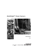

MultiSight™ User Manual
Installation Instructions
10000000877(02) 9
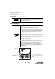
Sensor Display LED Description
Table 1: Table Display LEDs
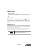
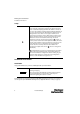
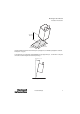
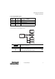
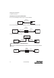
For electrical installation, connect the MultiSight as shown:
Name Color Meaning
Pwr. green
Operating voltage
Err. red
Error
Q1 yellow
Result 1 (pass/fail = OUT1)
Q2 yellow
Result 2 (position = OUT2)
Use only the correct connection cables as listed below (see
“Accessories” on page 67).
The Ethernet connection is only required for setup. During normal
operation, only the PWR and I/O cable needs to be connected (
unless using the EtherNet/IP functionality).
48MS
ENET
PC
PWR
I/O
PLC
ENET (a)
PWR and I/O (b)
E
IMPORTANT
E