
Owner's manual

MultiSight™ User Manual
Maintenance
66 10000000877(02)
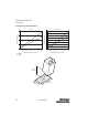
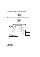
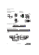
Connector Pin Assignments
PWR and I/O connector
Indicates sensor evaluation is valid for OUT1 and OUT2, except in special cases noted in the Configurable
Delays section on page 40.
Control Input IN2: if the Control Input parameter (Detector Parameter window) is set to Enable (default
setting), the control input IN2 must be connected to V+ (24V DC) for the sensor to operate. If the control
input IN2 is not connected to V+, the MultiSight will not execute evaluations if the trigger mode is set to
“triggered” (standby mode) (see page “Use of Control Input IN2” on page 58).
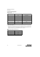
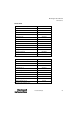
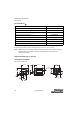
Ethernet M12 D-Code 4-Pin Connector
Pin (M12) Color Use
1 White IN1 (external trigger)
2Brown 24V DC (V+)
3 Green OUT1 (pass/fail); display LED = Q1
4Yellow
OUT4 (ready)
5 Grey IN2 (control input)
6PinkOUT3 (external illumination trigger)
7Blue GND (V-)
8RedOUT2 (position); display LED = Q2
Pin (M12 D-Code) Use
1Tx+
2Rx+
3Tx-
4Rx-
E