
Owner's manual
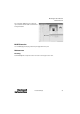

MultiSight™ User Manual
Maintenance
58 10000000877(02)
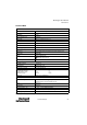
Technical Data (continued)
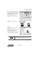
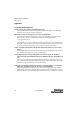
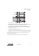
Use of Control Input IN2
This section details the operation of the control input IN2
Enable (Case 1 on page 60)
Activate 0 or 1 (Case 2)
Activate 0 to 31 (Case 3)
Teach temporary (Case 4)
Teach permanent (Case 4)
For the signal sequence see the diagram below. Pin assignments are on page 66.
Connections PWR and I/O connector M12, 8 pins; Ethernet M12, 8 pins
Ethernet M12, 4-pins, D-code
Housing Material aluminum, plastic
Functions and Characteristics
Number of test detectors per sensor
up to 10 ( 32) detectors with definable parameters for each
Detector Types • pattern match with/without position detection
•area test brightness
•area test contrast
• contour match with/without position detection
• position data (via EtherNet/IP only)
Typical cycle time Pattern matching: 50…100 ms
Contrast or brightness area test: 40…50 ms
Contour matching: 120…500 ms
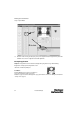
For operation using the control input, set the “Control Input”
parameter in the “Detector parameters” window as described
below.
The detector which is activated by “Reset” or “Power on” is the
one which was activated most recently using the radio buttons in
the window “Select detector” of the PC software or via
EtherNet/IP.
E
E
E
E
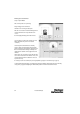
IMPORTANT
E