
Owner's manual
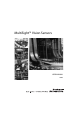

MultiSight™ User Manual
Description of Operation
10000000877(02) 5
Performance Features
• Vision sensor
• Easier handling and setup than traditional vision systems
• 640 x 480 resolution CCD chip
• Integrated white-light illumination
• Image display on computer using included software
• Standalone sensor function
• Compact, sturdy, industrial housing (IP67) with standard 8-pin micro (M12) QD connectors
• Detection distance adjustable from 20 mm to infinity (see “Minimum Operating Distance and Field of View by Cat. No.” on
page 63 for corresponding field of view)
• Four outputs (PNP type sourcing MOSFETs), two inputs (sinking)
• Short evaluation time
• Three (or four) evaluation methods: Pattern Matching, Brightness, Contrast, and Contour Matching
• Ten virtual detectors or 32 virtual detectors
• Individual virtual detectors can be logically linked or grouped for evaluation of different objects with several characteristics
for inspection
• Ethernet connection for setup
• EtherNet/IP connection for communication of I/O information
• RSLogix 5000 Add-on Profile for ease of integration into a Logix-based control system
Description of Operation
Basics
The image recorder of the MultiSight is a CCD chip with a resolution of 640 x 480 pixels. Evaluation is based on 320 x 240 scanning
points. The sensor is designed for inspection and cannot provide measurement information. To operate the MultiSight, at least one
virtual detector must be configured by designating a Region of Interest and teaching a sample image (see screen shot on page 20).
This virtual detector is stored in a non-volatile flash memory on the sensor and is re-activated for standalone operation after
switching off and on. Standalone operation is, therefore, possible with or without PC or PLC.
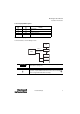
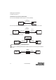
Evaluation Method
During operation, the MultiSight continuously compares the pattern of the detected image with that of the reference image. The
pixel grey-scale values of the sample are analyzed and a level of conformity to the original sample is determined. If this level falls
within the user adjustable threshold settings, the sensor turns the PNP output ON or OFF (i.e., the part passes or fails the inspection).
The EtherNet/IP connection is capable of communicating additional data about the inspection.
E
E
E
E
E
E