
Owner's manual

MultiSight™ User Manual
Start-up
10000000877(02) 29
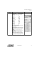
Parameter Description Screen Shot
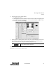
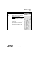
Logic (continued)
Select radio buttons 0-9 ( 0-31) in order to configure the
parameters for that detector. Detectors that are logically linked
should follow these guidelines for the Detector Parameter
configurations:
Detector Type any
Illumination identical
Resolution/Speed any
Zoom identical
Control Input identical
Trigger Mode identical
Shutter Adjustment manual
Position Control any
Shutter identical
Trigger Delay identical
Output Delay identical
Output Duration identical
Output Active identical
Threshold
Min any
Threshold Max any
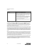
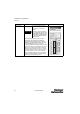
The Logic field has the following options:
None—No logical link or grouping, i.e. only the selected detector
determines the output.
AND (All) and OR (Search)—The inspection output OUT1 (pass/
fail) is based on the evaluation of all detectors selected via the left-
hand check box. (In the screen shot, detectors 1-6 are logically
linked.)
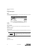
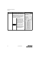
AND (All)—OUT1 is active if ALL selected detectors pass
evaluation
OR (Search)—OUT1 is active if ANY of the selected detectors
passes evaluation
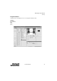
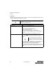
AND and OR (group)—The group functionality allows the
MultiSight to make several different inspections on multiple parts
without reconnecting to the software to change between the
parts. (This functionality is described more thoroughly above in the
general description of the Select Detector window.)
E