MultiSight™ Vision Sensors USER MANUAL 48MS
Important User Information In no event will Rockwell Automation, Inc. be responsible or liable for indirect or consequential damages resulting from the use or application of this equipment. The examples and diagrams in this manual are included solely for illustrative purposes. Because of the many variables and requirements associated with any particular installation, Rockwell Automation, Inc. cannot assume responsibility or liability for actual use based on the examples and diagrams.
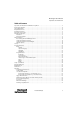
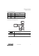
MultiSight™ User Manual Important User Information Table of Contents Important User Information and Definition of Symbols . . . . . . . . . . . . . . . . . . . . . . . . . . . . . . . . . . . . . . . . . . . . . . . . . . . .2 Components Supplied . . . . . . . . . . . . . . . . . . . . . . . . . . . . . . . . . . . . . . . . . . . . . . . . . . . . . . . . . . . . . . . . . . . . . . . . . . . . . . . . . . . .4 Typical Applications . . . . . . . . . . . . . . . . . . . . . . . . . . . . . . . . . . . . .
MultiSight™ User Manual Components Supplied Components Supplied • • • • Bulletin 48MS MultiSight vision sensor with integrated lighting Computer software on CD-ROM Installation instructions, mounting bracket 48MS-BKTDT with three screws, Allen wrench, screwdriver, and protective cap for M12 Ethernet connector. E Two PVC M12 QD covers (must be installed around the metal coupling nuts of both connection cables for ESD protection).
MultiSight™ User Manual Description of Operation Performance Features • • • • • • • • • • • • • • • • Vision sensor Easier handling and setup than traditional vision systems 640 x 480 resolution CCD chip Integrated white-light illumination Image display on computer using included software Standalone sensor function Compact, sturdy, industrial housing (IP67) with standard 8-pin micro (M12) QD connectors Detection distance adjustable from 20 mm to infinity (see “Minimum Operating Distance and Field of View
MultiSight™ User Manual Installation Instructions Setup The PC must be connected to a MultiSight sensor via the Ethernet port to load the configuration software. Also, Run mode of the sensor is automatically stopped when the software connects to the sensor. The software is tightly integrated with the firmware on the sensor. As parameters are changed in the software they are changed in the sensor.
MultiSight™ User Manual Installation Instructions Operating Distance Width of Field of View Height of Field of View The height and width of the field of view is determined by the operating distance (see “Minimum Operating Distance and Field of View by Cat. No.” on page 63). For most applications, it is recommended to align the MultiSight at an angle of approximately 10…15° with reference to the optical axis in order to avoid interfering reflections from the inspection target. Approx.
MultiSight™ User Manual Installation Instructions Fine Adjustment IMPORTANT Fine adjustment of the MultiSight should not be carried out until after electrical connection and start-up (PC software installation) (see “Start-up” on page 18). Electrical Installation The electrical installation of the MultiSight must be carried out by a qualified electrician. When installing the MultiSight disconnect all electrical components from the power supply.
MultiSight™ User Manual Installation Instructions Sensor Display LED Description Name Color Pwr. green Meaning Operating voltage Error Err. red Q1 yellow Result 1 (pass/fail = OUT1) Q2 yellow Result 2 (position = OUT2) Table 1: Table Display LEDs For electrical installation, connect the MultiSight as shown: PC ENET (a) 48MS PWR and I/O (b) ENET E PLC I/O PWR IMPORTANT Use only the correct connection cables as listed below (see “Accessories” on page 67).
MultiSight™ User Manual Installation Instructions Network Connection (a) for standard models Direct connection of the MultiSight to a PC with a single crossover cable (recommended): Ethernet Cross-over Cable 48MS-ECSCROSS-3 48MS M12 RJ45 PC Direct connection of the MultiSight to a PC with an industrial ethernet cable and a separate standard RJ-45 crossover cable: Ethernet Connector 48MS-RJ45Conn 48MS M12 Ethernet Cable 48MS-ECS-3 RJ45 Ethernet Cross Cable 48MS-Ecross RJ45 PC RJ45 Connection of
MultiSight™ User Manual Network Settings E Connection of the MultiSight with EtherNet/IP to a PC and PLC via a network: Network e.g.
MultiSight™ User Manual Network Settings Basic Settings for PC and MultiSight To configure the MultiSight Sensor with a PC it is essential that Ethernet capability is installed in the PC and the LAN connection on the PC is active with a TCP/IP protocol. This also applies when the PC is not connected to a network (see “Network Connection” on page 8). In addition, every machine in the network must be allocated a unique IP address.
MultiSight™ User Manual Network Settings To set the IP address of the computer carry out the following procedure in the operating system: 1. Click on the “Start” button on your computer. 2. Click on “Settings” 3. Click on “Network Connections” 4.
MultiSight™ User Manual Network Settings 5. Click on “Properties” 6. Click on “Internet Protocol TCP/IP” properties 7.
MultiSight™ User Manual Network Settings Setting the IP Address of the MultiSight IMPORTANT Contact the system administrator to determine which IP addresses are allowed on your network for the MultiSight. The IP address set for the MultiSight should be marked on the enclosed label. After installation, stick the label on the sensor in a clearly visible position.
MultiSight™ User Manual Network Settings Creating a Functioning Ethernet Connection Between a PC and a MultiSight 1. Direct connection (see “Electrical Installation” on page 8) All cables correctly connected? 24V DC Power Supply? no Connect all cables correctly 1. Power and I/O cable 2.
MultiSight™ User Manual Network Settings no Connect all cables correctly 1. Connecting cable 2. Ethernet cable (straight) All cables correctly connected? yes no Electrical connection ok? MultiSight Pwr LED on Network: Start/Settings/Network connections No red X on Local Area Connection yes Obtain IP address for sensor from system administrator If necessary execute IPConfig.
MultiSight™ User Manual Start-up Firmware Update IMPORTANT Before using the Update function, consult your Support group and use only the original update files from the manufacturer. The execution of the function must not be interrupted as this may cause failure of the MultiSight. The stored detector configurations are deleted by the update and must be redefined when the function is concluded. This function allows you to update the software of the MultiSight.
MultiSight™ User Manual Start-up To start the MultiSight, proceed as follows: 1. Switch on the power supply (24V DC) for the MultiSight. If necessary, connect the control input (IN2) with V+ (24V DC) (see note on page 11). 2. For the first start-up of the MultiSight, install the supplied software on the computer that will be used for configuring the sensor. When the CD is inserted, the installation program starts automatically or can be started using the setup program / Software/ MultiSight.exe.
MultiSight™ User Manual Start-up 6. Click the desired sensor to select it in order to Connect, SetIP, or Update. Click the Connect button in order to establish a network connection with the sensor and start the configuration software. If no sensor can be found with the Find command, it is possible to connect manually with function “Add IP” by filling in the known IP-address of the sensor. 7. Click “Yes” to stop Run mode of the MultiSight and connect to the sensor. 8.
MultiSight™ User Manual Start-up 11. If no live image appears, check to confirm the following: a. No obstruction in front of the lens. b. Sufficient lighting. Detector Parameter “Illumination” should be “Internal ON” or sufficient external lighting provided. c. Correct shutter settings (under Detector Parameters—see screen shot). Increase shutter time to brighten the image. d. Correct focus—focus screw on back of MultiSight. 5.
MultiSight™ User Manual Start-up Program Description Menu The menu for the PC program has main and subsections. These are selected by clicking the desired menu item or by pressing the ALT key and the first letter of the menu item at the same time. File/Exit Exit program. Options/Language Select language. The new language does not take effect until the software is restarted. (Currently English is the only available language.
MultiSight™ User Manual Start-up Program Interface The program interface is entirely displayed on one screen.
MultiSight™ User Manual Start-up Commands The buttons shown along the left hand side of the screen are for the general operation of the MultiSight, administration of detector configuration and displaying other information on the program. If a button is not active (i.e., greyed out) then that command is not available in the current mode. Command Connect/Disconnect Description Connect to or disconnect from MultiSight (see Setup).
MultiSight™ User Manual Start-up Command Run/Stop Description Run Evaluation mode (MultiSight is automatically in Run mode when not connected to the software) Stop Configuration mode. Configuration parameters can only be changed in this mode. Trigger Manual triggering of MultiSight image evaluation (active only in “Run” mode and if Trigger parameter is set to “triggered” (see “Detector Parameters” on page 32) or when triggered image button in image section is pushed).
MultiSight™ User Manual Start-up Command Recorder Images Description Transfers the images saved on the MultiSight to the computer. The MultiSight can save up to 30 images on its local memory. To save images, the Recorder parameter in the Select Detector window must be turned on (see page 27). Based on the setting of that parameter, the MultiSight can save either the last 30 images or the last 30 images of inspections that resulted in an output of FAIL.
MultiSight™ User Manual Start-up Parameter Description Sensor name Assign a name for the connected MultiSight. This name appears in the MultiSight Sensor Finder software and allows for easier identification of the correct sensor when multiple MultiSight sensors are on a single network. Live Images When this checkbox is selected, the live image is displayed in the Image window of the software during Run mode.
MultiSight™ User Manual Start-up Parameter Logic Description The Logic field allows the user to define how the detectors are linked together to determine the single OUT1 (pass/fail) output. A detector can be standalone (inspection of a single characteristic), logically linked (multiple inspections on a single part), or grouped (multiple inspections on different parts). (The concept is more thoroughly described in the above general description of the Select Detector window.
MultiSight™ User Manual Start-up Parameter Logic (continued) Description Screen Shot Select radio buttons 0-9 ( E 0-31) in order to configure the parameters for that detector.
MultiSight™ User Manual Start-up Parameter Description Logic (continued) Screen Shot In order to use the grouping functionality, Detector Parameter Control Input must be set to “Activate 031” for ALL active detectors. IMPORTANT The same Logic is applied to each Group of detectors. Example: if the detectors in Group A are logically linked with AND, the detectors in Group B will be logically linked with AND. It is not possible to link Group A with AND and Group B with OR.
MultiSight™ User Manual Start-up Parameter Description Radio buttons 0…9 ( E 0…31) Designates the active detector—by clicking one of the ten radio buttons, the corresponding detector is selected and its parameters can be configured. The parameters are displayed in the Detector Parameters window in the middle of the screen. Only one detector can be configured at a time. After restart, the most recently selected detector is active.
MultiSight™ User Manual Start-up Detector Parameters To configure a detector, select the appropriate radio button in the Select Detector window and then set the parameters in the Detector Parameters and Image windows. Each detector is configured independently. (Detector parameter configurations can be copied into other detector parameters using the Copy command, see page 24.
MultiSight™ User Manual Start-up Parameter Control Input Description The settings for the Control Input are described in detail on page 58) Enable Teach temporary Activate 0 or 1 Activate 0 to 31 Teach permanent If this parameter is set to Enable (the default setting), the I/O control input IN2 must be connected to V+ (24V DC). (This is in addition to a trigger input on IN1 (external trigger)).
MultiSight™ User Manual Start-up Parameter Description Shutter x.xx ms Exposure time: slide for setting shutter value manually. Increase to brighten image; decrease to darken image. The shutter speed can also be adjusted by clicking on the number and typing a new value into the pop-up window. Trigger Delay (ms) Time between trigger and exposure/evaluation in 0-3000 ms (see “Configurable Delays” on page 40).
MultiSight™ User Manual Start-up Detector Types—Detailed Description The following detector types are available: Pattern Matching, Brightness, and Contrast. E The EtherNet/IP model also has a Contour Matching detector type. Pattern Matching With this method, the detector looks for a pattern in a defined Region of Interest (ROI). By defining this ROI as larger than the pattern there is some tolerance in positioning of the inspected part.
MultiSight™ User Manual Start-up For example, here is the same image with three different shutter speeds: Region of Interest: Shutter setting: The setting of the threshold determines the maximum number of pixels detected as being dark which is required to pass the evaluation. The position of each dark pixel within the ROI does not affect the evaluation. Example: These two images produce exactly the same result in the brightness evaluation because in each case 9 of the 25 pixels are detected as dark.
MultiSight™ User Manual Start-up Contour Matching The Contour Matching detector type is essentially a simplified pattern matching algorithm. Instead of the fully detailed pattern with relative grey scale levels and complex area evaluation used for comparison in the Pattern Matching detector type, the Contour Matching detector type compares simple line contours and shapes. In contour mode, the teach process identifies the borders between dark and bright areas on the image.
MultiSight™ User Manual Start-up Parameter Description Edge contrast1 Difference in grey-scale value. Minimum difference in grey scale value to define a line contour, i.e. the min. difference between bright and dark areas to get a blue contour line. Defined in terms of 8 bit grey scale value Value range = 7…128, default = 50. Edge gradient1 Edge steepness. Maximum number of pixels for the edge width, within which the above edge contrast difference should take place. Value range = 6…19, default = 12.
MultiSight™ User Manual Start-up Parameter Description Min. scaling2 Minimum factor for scaling the size of the contour. Values = 0.5 … 1.0, default = 1.0 Max. scaling2 Maximum factor for scaling the size of the contour. Values = 1.0 … 1.5, default = 1.0 Starting angle2 Angle at which the search starts. Search in clockwise direction. Values = -180° … 179°, default = -10° 0° = 12:00am on a clock Total angle2 Maximum search angle.
MultiSight™ User Manual Start-up Configurable Delays There are three timing mechanisms that can be used: Trigger Delay, Output Delay, and Output Duration. Each has a range of 0…3000 ms. The following timing diagrams show the behavior of the outputs for each timing mechanism condition.
MultiSight™ User Manual Start-up Case 3) Output Delay = Time (in ms) between the Trigger and the availability of results from Output 1+2 (Pass/Fail). Note that the Output Delay must be longer than the evaluation time. IN1 (Trigger) Output Delay (Includes Evaluation Time) OUT4 (Ready/Busy) OUT 1+2 (Pass/Fail) Ready On " Ouput Valid Case 4) Output Duration = Duration (in ms) of the result output on Outputs 1+2.
MultiSight™ User Manual Start-up Special Case: Control of Outputs with Use of Output Duration Parameter Output Behavior with 0 ms Output Duration (default setting) Behavior with > 0 ms Output Duration OUT4 (Ready) This output shows when the sensor is ready to make an evaluation and when the results of the previous evaluation are valid. This output shows when the sensor is ready to make an evaluation but DOES NOT show when the results of the previous evaluation are valid.
MultiSight™ User Manual Start-up Screen Shot Field name Description Region of Interest (ROI) – Yellow frame with a number When a detector is selected (radio buttons in Select Detector window) its ROI appears as a yellow frame with a number on the image. The ROI can be selected by double clicking anywhere inside it. A dot will be displayed just outside each corner and along each side to indicate that it is selected.
MultiSight™ User Manual Start-up Screen Shot Field name Description Display: ROI, Pattern, and Position For currently non-selected detectors whose Display Icon check box is selected, the check boxes determine whether each respective frame is displayed on the image. Single Image (via Trigger) Allows the user to capture a single image initiated by the external (or software) trigger, including trigger delay parameter settings.
MultiSight™ User Manual Start-up Recommendations for selecting a pattern or contour: For reliable evaluation - The pattern/contour should have a unique characteristic— some aspect that does not occur on a “bad” part. - Patterns or pattern characteristics should have clear contours/ shapes. - Pattern/contour characteristics should NOT vary. - The pattern area should be set as large as possible within the image.
MultiSight™ User Manual Start-up Region of Interest Region of Interest Sensor Image Sensor Image Pattern Pattern Faster Slower Position Deviation Check and Frame Type Position control can be activated when the pattern matching or contour matching detector types are selected. If position control is selected, a blue frame is displayed on image screen.
MultiSight™ User Manual Start-up Pattern The Pattern window shows the taught pattern or contour for the currently selected detector. Save Pattern Saves the taught pattern (or contour) as a bitmap file (.bmp) Zoom Opens a window showing an enlarged version of the pattern (2:1 ratio, digital zoom) E Eraser size (contour matching only)—determines the size (in pixels) of the square eraser that can be used to edit the taught contour (which is depicted as a blue line).
MultiSight™ User Manual Start-up Field Result Bar Graph Description The degree of conformity of the current pattern with the pattern taught is shown as a bar graph. The status of the overall inspection is shown as a green (pass) or red (fail) dot. The result is determined by whether the degree of conformity is within the configured thresholds. For a standalone detector, the bar graph indicates the degree of conformity.
MultiSight™ User Manual Setup—Quick Guide Setup—Quick Guide Preparation 1. Double click the MultiSight software icon to launch the Sensor Finder software. 2. The Sensor Finder software will show ALL MultiSight sensors on the local Ethernet network. Select the sensor and set the IP address if necessary. The IP address and subnet mask of the PC is shown at the bottom of the window. 3. Select the MultiSight by clicking on its IP address. Establish the connection by clicking Connect.
MultiSight™ User Manual Setup—Quick Guide 7. Slowly adjust the manual focus on the back of the MultiSight using the small screw driver until the image comes into focus. You may need to adjust the shutter speed more to get the best image. The ideal is to have a high level of contrast and a sharp focus. 8. Click Stop in the Image window to exit live image mode. Define Search Criteria The next step is to position the Region of Interest (ROI) and Pattern frames.
MultiSight™ User Manual Setup—Quick Guide 11. In the Detector Parameters section (third column), change the Trigger Mode setting to Continuous (from Triggered). While in run mode, this will cause a new inspection to start as soon as the last one finishes. In the Select Detector section (second column), click the Live Images checkbox so that images will be displayed in the software while the sensor is connected. 12. Click the Teach button in the Commands section. Click Teach From PC Image.
MultiSight™ User Manual Setup—Quick Guide 14. Based on the results of several good and bad parts, you may need to adjust the threshold settings. Click the Stop button in the Commands section to return to configuration mode and make adjustments. Example Application Example: Detecting whether hex nuts are welded on mounting brackets by using the detector type “Pattern Matching.” During machine assembly, inspect mounting brackets to ensure that hex nuts are welded in specified places.
MultiSight™ User Manual Setup—Quick Guide When the MultiSight is powered up, the image shown in the “Image” section of the computer software is the last image recorded. For setting up a new inspection, click on the “Reset” Command button. To view and continuously update the live image, click the “Live Image” button. To bring the object into focus, turn the focusing screw on the back of the sensor. To improve the contrast, use the “Shutter” in “Detector Parameters.
MultiSight™ User Manual Setup—Quick Guide Click on the “Stop” button to stop live image. Change the trigger mode to “Continuous.” This makes it easier to check good and bad parts. Click on the “Teach” and select “Teach from PC image” button to teach the pattern. Click on the “Stop” button after a few seconds. Notice the taught pattern display in the “Pattern Section.” Select “Live Images” check box in the Select Detector section. Click the “Run” button. The pattern is now evaluated continuously.
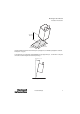
MultiSight™ User Manual RESET/Power On In the opposite figure, MultiSight sensor has evaluated the object as “bad.” Notice that the red LED is on and the hex nut is missing from the bracket. RESET/Power On To reset the MultiSight, pull out the plug or turn off the power supply and then restore power. Maintenance Cleaning Clean the MultiSight with a clean dry cloth. Do not use solvents. Do not use sharp objects. Do not scratch.
MultiSight™ User Manual Maintenance Appendix Frequently Asked Questions How do I change the IP address of the MultiSight sensor? Proceed as described in “Network Settings” and “Setting the IP Address of the MultiSight Sensor” sections on pages 11 and 15, respectively. What is the easiest way of testing the connection to the MultiSight? In the start menu of the operating system, click on “Run” and then “cmd.” In the window which appears, enter the command “Ping” and then the MultiSight IP address: e.g.
MultiSight™ User Manual Maintenance Technical Data Electrical Data Certifications cULus and CE Marked for all applicable directives Supply Voltage 24 V DC ± 10% (absolute maximum 18…30 V) Residual Ripple < 5 Vpp Current Consumption (no I/O) 200 mA, max. Inputs IN1/IN2 High 10 V…V+/24V DC (+10%), low 0…3 V Input Resistance > 20 kOhm Trigger Input rising edge, 10 V…V+/24V DC Outputs OUT1 - 4 PNP type (sourcing MOSFET) Output Rating (per output) 200 mA Output Current (per output) 1.
MultiSight™ User Manual Maintenance Technical Data (continued) Connections PWR and I/O connector M12, 8 pins; Ethernet M12, 8 pins E Ethernet M12, 4-pins, D-code Housing Material aluminum, plastic Functions and Characteristics Number of test detectors per sensor up to 10 ( E 32) detectors with definable parameters for each Detector Types • • • pattern match with/without position detection area test brightness area test contrast • E contour match with/without position detection E position data (vi
MultiSight™ User Manual Maintenance IN 1 (Trigger) 1 4 5 Out 4 (Ready) 2 Out 1 (Pass/Fail) 2a 3 A Activate 1 or 2 IN 2 (case 2) 1 or 2 IN 2 (case 3) Activate 0 to 31 B C Typ 5ms / 5ms IN 2 (case 4) Teach temp/perm. D E 1. Rising edge at IN1 (Trigger) starts sensor (triggers exposure and processing). 2. Trigger starts falling edge at OUT4 (Ready). Ready stays low for duration of evaluation.
MultiSight™ User Manual Maintenance Case 1: Control Input = Enable Control input = Enable means that IN2 must be connected to V+ (+24 V DC) to allow the external trigger. IMPORTANT If control input = enable (default state), IN2 (grey wire) MUST be connected to V+ (24V DC) for the external trigger to work. Case 2: Control input = Activate 0 or 1 This function allows the Control Input to determine whether detector 1 or detector 2 is evaluated.
MultiSight™ User Manual Maintenance When changing detectors, if a detector is selected that does not have the Control Input parameter set to Activate 0 to 31 (or Activate 0 or 1), it is not possible to change to another detector using the control input IN2. The control input has a different function and therefore is no longer capable of switching to another detector.
MultiSight™ User Manual Maintenance The save operation for permanent save (Teach permanent) may take up to 500 ms. IMPORTANT 62 During this period in continuous moving applications, the output locks to FAIL regardless of the part evaluation (i.e. both “good” and “bad” parts give a FAIL output). When the Teach Temporary function is used, the new pattern is stored only in the RAM (this requires much less time).
MultiSight™ User Manual Maintenance Trigger Mode Parameter Triggered or Continuous When “Triggered” is selected, the sensor initiates an exposure and evaluation when the external trigger IN1 transitions from low (GND) to high (V+/24V DC) or the “Trigger” command button in the computer software is clicked. When the “Continuous” Trigger Mode is selected, the sensor initiates a new exposure and evaluation as soon as the last evaluation is complete, i.e., the sensor cycles as fast as possible.
MultiSight™ User Manual Maintenance Field of View per Operating Distance 12 mm Lens 200 6 mm Lens 400 350 X X 300 Field of View—mm Field of View—mm 150 Y 100 50 250 Y 200 150 100 50 0 0 0 100 (3.93) 200 (7.87) 300 (11.8) 400 (15.7) 500 (19.6) 600 (23.6) 0 Operating Distance—mm (in) 100 (3.93) Operating Distance 64 300 (11.8) 400 (15.7) 500 (19.6) Operating Distance—mm (in) X = Width Y = Height Height of Field of View 200 (7.
MultiSight™ User Manual Maintenance Connection: M12 (Micro) 8-pin Male QD (both PWR and I/O and ethernet) 2 3 8 1 4 7 5 6 E Ethernet connection: M12 (micro) 4-pin D-code female quick disconnect (ethernet connection, EtherNet/IP model).
MultiSight™ User Manual Maintenance Connector Pin Assignments PWR and I/O connector Pin (M12) Color Use 1 White IN1 (external trigger) 2 Brown 24V DC (V+) 3 Green OUT1 (pass/fail); display LED = Q1 4 Yellow OUT4 (ready) 5 Grey IN2 (control input) 6 Pink OUT3 (external illumination trigger) 7 Blue GND (V-) 8 Red OUT2 (position); display LED = Q2 Indicates sensor evaluation is valid for OUT1 and OUT2, except in special cases noted in the Configurable Delays section on page 40
MultiSight™ User Manual Maintenance Accessories Product Descriptor Cat. No.
MultiSight™ User Manual Maintenance EtherNet/IP Model E Product Descriptor Cat. No.
MultiSight™ User Manual Maintenance MultiSight EtherNet/IP Models Dovetail Bracket—48MS-BKTDT (Included with MultiSight) Angle Bracket—48MS-BKTANG 5 (0.19) M4 23 (0.90) R2.25 (R.088) 9 (0.35) 35 (1.37) 10 (0.39) 60° 90° 3 (0.11) 4.5 (0.17) Dia. 10 (0.39) 35 (1.37) 15 (0.59) 8 (0.31) 10 (0.39) 20 (0.78) 1.8 (0.07) 60° 12.4 (0.48) 14.5 (0.57) 60° 10 (0.39) R2.25 (R.088) 14.25 (0.56) 4.5 (0.17) Dia. 10 (0.39) 20 (0.
MultiSight™ User Manual Maintenance Angle Bracket for Ring Light— 48MS-BKTANG2 Rod Bracket— 48MS-BKTROD 5 (0.19) R2.25 (R.088) 13 (0.51) 60° 90° 30 (1.18) 3 (0.11) 12.5 (0.49) 10 (0.39) 4.5 (0.17) Dia. 10 (0.39) 32 (1.26) 10 (0.39) 30 (1.18) 32 (1.26) 60° 10 (0.39) R2.25 (R.088) 14.25 (0.56) 20 (0.78) 4.5 (0.17) Dia. 10 (0.39 10 (0.39) M4 (10X) 20 (0.78) Mounting Rod 200—48MS-ROD200 200 (7.87) 12 (0.47) Dia. M6 Mounting Rod 400—48MS-ROD400 400 (15.74) M6 12 (0.47) Dia.
MultiSight™ User Manual Maintenance ALLE 48MSMADE Rod Clamp—48MS-CLAMP Mounting Plate—48MS-MTPLATE 150 (5.90) 100 (3.93) 50 (1.96) 20 (0.78) 20 (0.78) A A 11 (0.43) (4X) 6.8 (0.26) 10 (0.39) 6.3 (0.24) Dia.
MultiSight™ User Manual Maintenance Area Light (White Light)—48MS-ALWH 45 (1.77) Power 24 (0.94) 12.7 (0.50) 30.5 (1.20) OUT M12X1 43 (1.69) 30.5 (1.20) IN 31.4 (1.23) 22.65 (0.89) 11.6 (0.45) 22.5 (0.88) 14 13.1 (0.55) (0.51) 31.9 (1.25) Connector Pin Configuration 4 5 2 3 1 4 5 8 7 6 2 3 1 8 7 6 Ring Light (White Light)—48MS-RLWH 30° 25 (0.98) 65 (2.55) Dia. 12.7 (0.50) 10 (0.39) 35° 115 (4.52) Dia. 53.5 (2.
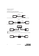
MultiSight™ User Manual Maintenance Mounting Set-up Illustrations Rod clamp Rod bracket Angle bracket Dovetail bracket Mounting rod Mounting plate Mounting rod Dovetail Bracket (48MS-BKTDT) Angle Bracket (48MS-BKTANG) Rod Clamp (48MS-RODLINK) Rod Bracket (48MS-BKTROD) Mounting Rod (48MS-RODxxx) Mounting Plate (48MS-MTPLATE) 10000000877(02) 73
MultiSight™ User Manual Maintenance 74 10000000877(02)
MultiSight™ User Manual Maintenance 10000000877(02) 75
www.rockwel lautomation.com Power, Control and Information Solutions Headquarters Americas: Rockwell Automation, 1201 South Second Street, Milwaukee, WI 53204-2496 USA, Tel: (1) 414.382.2000, Fax: (1) 414.382.