
User Manual

2
The 8 m & 50 m models of the 45LMS are Class 1 laser products.
A Class 1 laser is safe under all conditions of normal use. This
means the maximum permissible exposure (MPE) is impossible
to exceed.
The 15 m models of the 45LMS are Class 2 laser products. A
Class 2 laser is not safe to stare at continuously; however, the
blink reflex of the human eye will prevent eye damage, unless the
person deliberately stares into the beam for an extended period
of time.
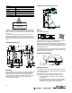
Dimensions [mm (in.)]
Mounting
Securely mount the sensor on a firm, stable surface or support for
reliable operation. A mounting subject to excessive vibration or
shifting may cause intermittent operation. The 45LMS-BKT1
mounting bracket is available for installation convenience. Once
securely mounted, the sensor can be wired per the wiring
instructions in the next section.
Interface
Interface type IO-Link
Protocol IO-Link V1.0
Cycle time Min. 2.3 ms
Mode COM 2 (38.4 kBaud)
Process data width 16 bit
SIO mode support Yes
8 m & 50 m MODELS
Laser Class 1
15 m MODELS
Laser Class 2
DO NOT STARE INTO BEAM
88
(3.47)
102
(4.02)
11
(.43)
6
(0.24)
62
(2.44)
93
(3.66)
10
(.39)
54.6
(2.15)
Ø5.2
(Ø0.205)
14.8
(0.58)
8
(0.32)
CLASS 1
LASER PRODUCT
Complies with 21 CFR
dated June 24, 2007
1040.10 and 1040.11 except
for deviations pursuant to
Laser Notice No. 50,
IEC 60825-1: 2007 certified
2
(0.08)
25.8
(1.02)
9
(0.36)
9.8
(0.39)
M12
23.8
(0.94)
12
(0.47)
18
(0.71)
54.9
(2.16)
7
(0.28)
A
A
Laser output
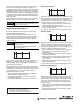
45LMS-BKT1 mounting bracket [mm (in.)]
Wiring
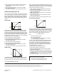
NPN or PNP (Push-Pull)
The 45LMS photoelectric sensor is available with a micro quick-
disconnect for ease of installation and maintenance.
Rockwell Automation recommends the use of the 889 Series of
cordsets and patchcords for quick-disconnect model sensors. All
external wiring should conform to the National Electric Code and
all applicable local codes.
The 45LMS features a Push-Pull discrete output. This means the
outputs always drive either 24V or 0V and can therefore be wired
like either an NPN or a PNP sensor.
Controls and indicators
Setting the sensor
The 45LMS is set up using the Rotary Switch and the SET button,
and it displays feedback via the Yellow and Green LED indicators
on the top of the sensor.
Upon completion of any set-point Teach, both LEDs flash
simultaneously, followed by alternating flashing of the LEDs.
• A successful Teach is indicated by a slower alternating
flashing (2.5 Hz).
• An unsuccessful Teach is indicated by a faster alternating
flashing (8 Hz). After an unsuccessful Teach, the sensor
continues to operate with the previous valid setting.
20
(0.787)
43
(1.69)
62
(2.44)
112
(4.41)
3
(0.12)
35
(1.38)
60°
5°
5°
5.3
(0.21)
R3.5
0.14
5.3
(0.21)
43
(1.69)
50
(1.97)
35
(1.38)
15
(0.59
)
30
(1.18)
5.3
(0.21)
5.3
(0.21)
5°
5°
35
(1.38)
1
3
4
2
3
4
2
1
Blue
Black
White
Brown
+
ANALOG
LOAD
−
(Q2)
(Q1)
A
B
Q1
A
B
Q2
RUN
SET
Yellow LEDs - Signal indicators
SET button
Rotary Switch
Laser output
Green LED
Operating indicator