
Manual

4
S Choose desired mode and slide set switch to RUN (settings
are now locked).
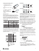
Setting Output Mode
Output Mode Options: Light On
Light On Off delay (40ms delay)
Dark On
Dark On Off delay (40ms delay)
S Slide switch to SET position
S Press and hold BLACK button for 3 seconds
S The display will show “SELE”
Operating Mode
Frequency/Channel Indicator
S Push the BLACK button until desired output is set
Light On
Light On
Off Delay
Dark On
Dark On
Off Delay
S Slide switch to RUN
Setting Interference Protection
S Slide switch to SET position
S Press and hold BLACK button for 3 seconds
S The display will show “SELE”
S Push the RED button to select Channel 1 or 2 for
transmission frequency selection for prevention of
interference between 2 sensors
S Set switch to RUN
Teaching the Sensor
Stationary Target
S Slide switch to SET (flashing “T”)
S Push and release RED button without target present
(Indicators flash to show standby status)
S Push and release RED button with target in position
(Flashing indicators stop flashing)
S Slide switch to RUN
S Setting is complete
Moving Target
S Slide switch to SET (flashing “T”)
S Push and hold RED button (Orange and Green LED
flashing alternately)
S While holding down RED button pass target in front of
sensor (LED flashing slows down)
S Release RED button when target finishes passing sensor
S Slide switch to RUN
S Setting is complete
Transmitted Beam Setting
S Set up opposing fibers
S Block light with target
S Slide switch to SET (flashing “T”)
S Push RED button twice
S Slide switch to RUN
S Setting is complete
Sensitivity Adjustment (Absolute Sensing Mode)
S Quickly flip switch from RUN to SET to RUN (“s” flashes to
show sensitivity adjustment status)
S Push RED button to decrease sensitivity
S Push BLACK button to increase sensitivity
S Unit automatically enters locked condition 10 seconds after
completion of adjustment
Sensitivity Adjustment (Relative Sensing Mode)
S Quickly flip switch from RUN to SET to RUN (“s” flashes to
show sensitivity adjustment status)
S Push BLACK button to decrease sensitivity
S Push RED button to increase sensitivity
S Unit automatically enters locked condition 10 seconds after
completion of adjustment
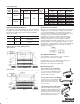
Dimensions—mm (inches)
Receiver
Transmitter
9
(0.35)
5 (0.2)
4.7
(0.19)
3
(0.12)
30
(1.18)
9
(0.35)
4 (0.16)
60 (2.36)
3
(0.12)
3
(0.12)
4.8
(0.19)
Dia.
4 (0.16)
21 (0.83)
16
(0.63)
36.5 (1.44)
11.5
(0.45)
2-3.2 (0.13)
Dia. hole
2-3.2 (0.13) x 5.2
(0.2) oval hole
21 (0.83)
16
(0.63)
Mounting Bracket
Cord
Bushing
Replacement Parts
S Plastic Sensor Cover: PSC1
S Fiber Optic Cable (Diffuse/Retro): 99–94
S Fiber Optic Cable (Transmitted Beam): 99–90
S Pico QD Cordset: 889P–F4AB–2
S Power Bus QD Connectors:
1 Conductor: 45F–A1C–A2
3 Conductor: 45F–A3C–A2
S Power Bus End Caps:
Male Cap: 45F–AMC
Female Cap: 45F–AFC
S 1.25mm fiber optic adaptor: 61–6731
Publication 75009–138–01(B)
May 2002
Printed in USA
PHOTOSWITCHR is a registered trademark
of Rockwell Automation.