
Manual


Publication GMSI10-UM031C-EN-E - July 2009
Index
Numerics
10 Base T 3, 15
A
AC coupling 7
ADC 3
address
Enwatch IP
11
HOST IP 13
HOST MAC 12
HOST UDP 13
IP network 11
analog inputs
1–16
5
AC coupling 7
DC coupling 7
DC voltage signal 19
ICP transducer 7, 17
jumpers 7
velocity sensor 18
analog-to-digital converter 3
anti-aliasing filter 2, 22, 33
B
Base 3
bias, transducer 2, 23
block diagram 1
block diagram component description 2
board diagram 4
C
clock generator 3
CMOS/TTL 7
coil-based velocity sensor
See velocity sensor
collection specification
26, 27, 29, 30
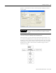
configuration with Emonitor 32
configuring Enwatch 11
connections
DC voltage signal
19
Ethernet 6
Hall effect sensor 20
ICP transducer 17
serial port 7
supply voltage 7
velocity sensor 18
connectors
J10
7
J11 10
J1–J11 5
J1–J2 5
J3–J6 6
J8 6
J9 7
D
data storage 32
DC coupling 7
DC measurements 25
DC voltage signal
jumper
19
wiring 19
diagrams
block diagram
1
board 4
DC voltage signal 19
Hall effect sensor 20
ICP transducer wiring 17
velocity sensor wiring 18
DSP functions and Enwatch driver 31
E
electrical components 2
electrical connections 4
enclosure 3