
Manual

Publication GMSI10-UM031C-EN-E - January 2009
18 Installing the Enwatch
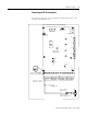
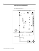
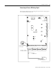
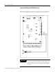
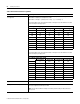
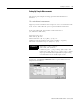
Connecting a Coil-Based Velocity Sensor
The following diagram shows the wiring from a coil-based velocity sensor to
the terminals of the Enwatch unit.
A - B
Network Input
RJ-45 Jack
Status LED's
RS-232
DB-9 (female)
DC Power In
J6
J5
J4
J3
JP 19
JP 18
JP 20
JP 21
JP 17
A - B
A - B A - B A - B A - B A - B A - B
A - B
A - B A - B A - B A - B A - B
A - B
A - B
TX
RX LK OB
+
_
J9
J8
J11
U28
U20
1 - 2 - 3 - 4 - 5 - 6 - 7 - 8 9-10-11-12-13-14-15-16 1 - 2 - 3 - 4 - 5 - 6 - 7 - 8
9-10-11-12-13-14-15-16
33
22
1
33
22
1
33
22
1
33
22
1
Normal / Monitor
Mode Select
RV2
RV3
RV1
4
3
2
1
TYPICAL WIRING FOR COIL-BASED VELOCITY SENSOR
Shield Ground
Terminal 1 - Signal
Terminal 2 - Ground
A - B
No Jumper for
Velocity Sensor
Pin A - Signal
Pin B - Ground
Cable shield not
connected at this end