
Manual

Publication GMSI10-UM031C-EN-E - January 2009
8 Installing the Enwatch
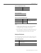
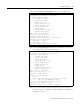
Each channel (16 total) has a 3-way header associated with it. These are labeled
with the channel number and “A” or “B.” The three jumper options are:
• Fitted to position xA
• Fitted to position xB
• Not fitted
where x is the channel number 1-16.
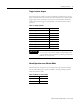
LEDs
Four LEDs, as shown in Figure 1.2 on page 4, indicate the status of the
Ethernet communication. These illuminate as described in Table 1.12.
Position Coupling
x A ICP
x B DC Coupled
Not Fitted AC Coupled
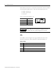
IMPORTANT
The -3dB point of the high-pass coupling for the ICP
interface and AC Coupled configuration is 0.07 Hz.
Table 1.12 LEDs
LED Description
OB The Enwatch unit is accessing LAN controller
LK Communication link is established between Enwatch unit and
network
RX Data is being received
TX Data is being transmitted
x B
x A