
Manual

Publication GMSI10-UM031C-EN-E - January 2009
Installing the Enwatch 7
Notes:
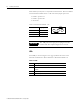
1. A supply voltage is available on pin 1 of the connector to power an
external trigger device. The voltage is equal to the voltage of the
incoming power supply to the board (on connector J9).
2. The external trigger is compatible with a CMOS/TTL logic level (5 V
logic). Alternatively, any voltage input in the range 5 to 24 V can be
accommodated. The trigger can be isolated or non-isolated.
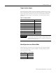
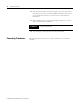
Analog Input Configuration
The 16 analog inputs provide you three options for signal coupling using a
3-way configurable jumper. The three positions are described in Table 1.11.
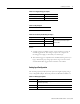
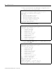
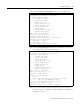
Table 1.8 J9 Supply voltage pin outputs
Signal Pin No.
Positive supply voltage +
Common -
Table 1.9 J10 pin outputs
Not user accessible
Table 1.10 J11 Serial port (RS-232) pin outputs
Signal Pin No. Notes
TXD 1 To connect to a host computer, use a
null modem 9-pin female to 9-pin
female cable.
RXD 2
Ground 3
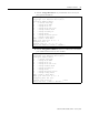
Table 1.11 Analog input options
Position Description
ICP Interface (nominal 24 V supply at 3.6 mA constant current for
transducer powering)
DC DC coupled
AC AC coupled