Enwatch Installation Guide
Important User Information Solid state equipment has operational characteristics differing from those of electromechanical equipment. Safety Guidelines for the Application, Installation and Maintenance of Solid State Controls (Publication SGI-1.1 available from your local Rockwell Automation sales office or online at http://www.ab.com/manuals/gi) describes some important differences between solid state equipment and hard-wired electromechanical devices.
Table of Contents Important User Information . . . . . . . . . . . . . . . . . . . . . . . . . . . . . . . . . . ii Table of Contents Installing the Enwatch Chapter 1 Introduction . . . . . . . . . . . . . . . . . . . . . . . . . . . . . . . . . . . . . . . . . . . . . . . 1 Installation . . . . . . . . . . . . . . . . . . . . . . . . . . . . . . . . . . . . . . . . . . . . . . . . 2 Electrical. . . . . . . . . . . . . . . . . . . . . . . . . . . . . . . . . . . . . . . . . . . . . . . 2 Mechanical . . .
Table of Contents iv Publication GMSI10-UM031C-EN-E - July 2005
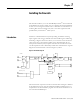
Chapter 1 Installing the Enwatch This manual introduces you to the Allen Bradley Enwatch® unit. The manual is intended for anyone who installs, tests, or configures the Enwatch hardware. It does not cover using the Enwatch unit to collect data. For information on collecting data with the Enwatch unit, refer to the Online Applications Guide provided with your Emonitor® online system. Enwatch is a distributed network system providing 16 channels of analog inputs together with 4 trigger channels.
2 Installing the Enwatch Installation The Enwatch unit is easy to install. The enclosure is mounted using four screws. Cables are terminated on removable screw terminal blocks, making installation and service simple. Network cables are terminated on the board using a a standard RJ-45 connector. Each Enwatch board has four status LEDs to monitor system activity.
Installing the Enwatch 3 • Analog-to-digital converter (ADC) - The ADC samples up to 51.2 kHz and has 16-bit resolution, providing a theoretical dynamic range of 96 dB. • Clock generator - The timer varies the sampling rate under microprocessor control. Sampling can be synchronized to one of 4 external triggers (typically a once-per-rev TTL signal from a rotating shaft). This system can also take a preprogrammed number of samples per revolution.
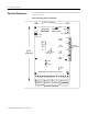
4 Installing the Enwatch Electrical Connections This section describes the electrical connections on the Enwatch board, shown in Figure 1.2, below. Figure 1.2 Enwatch electrical connections 6.
Installing the Enwatch 5 Connectors The Enwatch unit has 11 connectors labeled J1 to J11 as shown in Table 1.1. Table 1.1 Enwatch connectors Connector No.
6 Installing the Enwatch Table 1.3 J3 External trigger pin outputs Signal Pin No. Notes Power supply 1 See note 1 on page 7. Input 2 See note 2 on page 7. Ground 3 Table 1.4 J4 External trigger pin outputs Signal Pin No. Notes Power supply 1 See note 1 on page 7. Input 2 See note 2 on page 7. Ground 3 Table 1.5 J5 External trigger pin outs Signal Pin No. Notes Power supply 1 See note 1 on page 7. Input 2 See note 2 on page 7. Ground 3 Table 1.
Installing the Enwatch 7 Table 1.8 J9 Supply voltage pin outputs Signal Pin No. Positive supply voltage + Common - Table 1.9 J10 pin outputs Not user accessible Table 1.10 J11 Serial port (RS-232) pin outputs Signal Pin No. Notes TXD 1 RXD 2 To connect to a host computer, use a null modem 9-pin female to 9-pin female cable. Ground 3 Notes: 1. A supply voltage is available on pin 1 of the connector to power an external trigger device.
8 Installing the Enwatch Each channel (16 total) has a 3-way header associated with it. These are labeled with the channel number and “A” or “B.” The three jumper options are: • Fitted to position xA • Fitted to position xB • Not fitted where x is the channel number 1-16. xB Position Coupling xA ICP xB DC Coupled Not Fitted AC Coupled IMPORTANT xA The -3dB point of the high-pass coupling for the ICP interface and AC Coupled configuration is 0.07 Hz. LEDs Four LEDs, as shown in Figure 1.
Installing the Enwatch 9 Trigger Isolation Jumpers Four jumpers, JP17 to JP20, are sited on the board to enable the four trigger inputs to be isolated or non-isolated. Non-isolated means the common of the trigger input can be connected to the common of the Enwatch unit. With a jumper removed, the trigger is isolated. Table 1.13 summarizes the jumper positions. Table 1.
10 Installing the Enwatch Serial Port (RS-232) An RS-232 compatible serial port is available on connector J11 for providing local communication with the board (independent of the Ethernet network). Only RXD and TXD lines are supported, and so a null modem cable must be used. An on-board software monitor is provided to communicate through the serial port. If you do not use a 9-pin female to female null modem cable, the recommended cable connection to a PC is shown in Table 1.15. Table 1.
Installing the Enwatch 11 Flash Memory If it is necessary to change the firmware, the flash memory is located in position U20 and U28 (see Figure 1.2 on page 4). This flash memory is socket mounted to allow you to change the EPROM. Make sure that the orientation of the chip is correct when installing. On Board Monitor When you insert a jumper into JP21, the Enwatch unit operates in its internal monitor mode. This enables you to change the IP address as well as modify other options.
12 Installing the Enwatch 4. Turn on the Enwatch unit. It should display its configuration, then a configuration menu in the terminal window. ---------- Start monitor com port: COM1 9600 Intelligent Transducer Adapter Type 1) V 1.2 Copyright Icon Research Ltd 1998/99 Main Menu: 1 - Exercise Hardware Control 2 - Exercise Memory Devices 3 - Exercise Ethernet Controller 4 - Exercise Combined Sub-Systems 5 - Configure Adapter Settings 6 - Enter Download Mode Make your selection (1-6) : 5 N81 5.
Installing the Enwatch 13 7. Select 3 - Assign Host IP, and set your Enwatch unit to one of your plant specific IP addresses. Intelligent Transducer Adapter Type 1) V 1.
14 Installing the Enwatch 9. Select 5 - Assign Subnet Mask, and set it to the number obtained from the IT department. Normally it is 255.255.255.000 Intelligent Transducer Adapter Type 1) V 1.
Installing the Enwatch 15 11. Select 8 - Assign Network Option, and set it to the 10 Base T Port. Intelligent Transducer Adapter Type 1) V 1.
16 Installing the Enwatch 14. Shut down the Enwatch unit by removing the AC power, then remove the jumper in the center of the board (JP21) and connect the board to an active Ethernet connection. You do not have to disconnect the RS-232 port. 15. Open a DOS prompt on a networked computer. Type ping, then a space, and then the first IP address. EXAMPLE ping 200.100.200.100 16. You should get a return response from the Enwatch unit.
Installing the Enwatch 17 Connecting an ICP Accelerometer The following diagram shows the wiring from an ICP accelerometer to the terminals of the Enwatch unit.
18 Installing the Enwatch Connecting a Coil-Based Velocity Sensor The following diagram shows the wiring from a coil-based velocity sensor to the terminals of the Enwatch unit.
Installing the Enwatch 19 Connecting an Process DC Voltage Signal The following diagram shows the wiring from a process DC voltage signal to the terminals of the Enwatch unit.
20 Installing the Enwatch Connecting a Magnetic Hall Effect Sensor The following diagram shows the external trigger wiring from a magnetic Hall effect sensor (magnetic interrupter) to the terminals of the Enwatch unit.
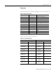
Installing the Enwatch Enwatch Measurement Capabilities 21 This section lists the measurement capabilities of the Enwatch unit. Table 1.16 Enwatch measurement capabilities Product Feature Capability Signal Control Raw input signal Integrated input signal via HP filter Hp filter input signal gSE 200 Hz input signal gSE 5000 Hz input signal Bias Voltage Combining measurements in the Enwatch driver The Enwatch driver can combine measurements at the same location in Emonitor.
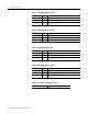
22 Installing the Enwatch Table 1.16 Enwatch measurement capabilities Product Feature Capability Sampling rate 64 to 51200 Hz by 1 FMAX Sampling Rate FMAX Sampling Rate 25 64 2000 5120 50 128 3200 8192 100 256 4000 10240 200 512 5000 12800 400 1024 6400 16384 500 1280 8000 20480 800 2048 10000 25600 1000 2560 16000 40960 1600 4096 20000 51200 Number of synchronous time averages 1, 2, 4, 8, 32 ...
Installing the Enwatch 23 Table 1.16 Enwatch measurement capabilities Product Feature Capability gSE time constant 0.03, 0.006, 0.0012, 0.00024 seconds, the default is 0.03 seconds if FMAX > 350Hz set to 0.00024 seconds else if FMAX > 150 Hz set to 0.0012 seconds else if FMAX > 37.5 Hz set to 0.006 seconds If the measurement is overall only (no spectrum) then set to 0.03 seconds. Integrator One level of hardware integration The hardware has a gain factor of: 2.67/f for the 0.36 Hz and the 2.
24 Installing the Enwatch Table 1.16 Enwatch measurement capabilities Product Feature Capability Maximum number of averages that can be supported Number of samples required: Lines x 2.56 + lines x 2.56(#avg -1) x (1 -%overlap) Max number of samples per configuration: 32768 Max number of averages = ((32768 / (lines x 2.56)) - 1) / (1 -%overlap) + 1) The following table shows the maximum number of averages versus the number of lines and percent overlap for non-trigger point.
Installing the Enwatch 25 Setting Up Sample Measurements This section gives examples of setting up measurement definitions in Emonitor. DC or other Numeric measurements Suppose you have a transducer with an output of -2 V to 2 V and a linear scale from -10° F to 100° F.
26 Installing the Enwatch Then select Setup>Transducer to select the “Temperature” transducer in the collection specification. In Emonitor, define a numeric measurement definition with the temperature units and the “Temperature” collection specification. Transducer bias reading Enwatch can take transducer bias readings; however, this is not a transducer check function that detects transducer failure before taking data.
Installing the Enwatch 27 Then select Setup>Calibration to select “Bias Voltage” as the input type for this transducer. The calibration should set to 1000 and the offset to 0. Then select Setup>Collection to define a new collection specification. Select “Transducer Check” as the transducer. In Emonitor, define a numeric measurement definition with Vdc units and the “Transducer Bias” collection specification.
28 Installing the Enwatch Saving the machine speed with a spectrum In the Hardware Setup program, when adding or editing an Enwatch unit, click the Trigger Channel tab. The Timeout is defined in seconds (the default is 5 seconds). The Number of pulse per rev default is 1 pulse per revolution. Click the Channel tab and assign the correct Trigger channel to the vibration channel. This example uses trigger channel 1 for the measurement on input channel 1.
Installing the Enwatch 29 Magnitude and phase reading A magnitude/phase reading is similar to any other data collector in Emonitor. You set up an overall measurement, using the “Mag & Phase” collection specification. Then select “1st Order” as the measurement filter (or any other desired order).
30 Installing the Enwatch You can reference any channel and there is no order you need to follow. Order normalized measurements You enable order normalized measurements in the collection specification. In Emonitor, select Setup>Collection. Then either edit an existing collection specification or create a new one. Make sure the Order normalization checkbox is selected.
Installing the Enwatch 31 applies it to the number of orders to select the proper sampling rate before collecting data. IMPORTANT You must also define a trigger channel for the Enwatch channel so that the Enwatch unit can find the machine speed. How are DSP functions handled in the Enwatch driver? The Enwatch unit only takes time domain data and returns that data to the host software. All DSP functions are done by the host driver. In this way, the firmware can focus on data collection speed.
32 Installing the Enwatch Limitation on number of points in Enwatch The Enwatch unit has 640 K bytes memory for data storage. If you attempt to collect data on more points than can fit in memory, the unit returns an error message. The message appears in the Unload Station Manager window (refer to the Online Applications Guide for more on the Unload Station Manager). The Enwatch driver can combine measurements in some cases (see “Combining measurements in the Enwatch driver” on page 21).
Chapter 2 Specifications This chapter lists the technical specifications for the Enwatch unit. Enwatch Technical Specifications Product Feature Specification Inputs Number of Channels 16 vibration and 4 tachometer (synchronizer) Voltage Protection Protects against over-voltage (channel auto-switch off) 2000 V ESD protection Input Impedance 1 MOhm Ranges ±10 mV to ±10 V, 7 ranges (software selectable) ICP Interface 3.
34 Specifications Enwatch Technical Specifications Product Feature Specification Spike Energy Measurement gSE Filters High pass at 200 Hz & 5 kHz 2nd order Trigger Types TTL Isolated or Non-Isolated, or any voltage up to +24 V Maximum combined current for all channels, not to exceed 100mA Machine Speed Range 1 to 60,000 RPM Time to Lock 2 revolutions Averaging 1, 2, 4, ...
Specifications 35 Enwatch Technical Specifications Product Feature Specification Communications Network Ethernet Medium 10BASE-T Connectors Weidmuller terminal blocks Speed 10 Mbits/sec Isolation 1000 Vrms Publication GMSI10-UM031C-EN-E - July 2009
36 Specifications Publication GMSI10-UM031C-EN-E - July 2009
Index Numerics 10 Base T 3, 15 A AC coupling 7 ADC 3 address Enwatch IP 11 HOST IP 13 HOST MAC 12 HOST UDP 13 IP network 11 analog inputs 1–16 5 AC coupling 7 DC coupling 7 DC voltage signal 19 ICP transducer 7, 17 jumpers 7 velocity sensor 18 analog-to-digital converter 3 anti-aliasing filter 2, 22, 33 B Base 3 bias, transducer 2, 23 block diagram 1 block diagram component description 2 board diagram 4 C clock generator 3 CMOS/TTL 7 coil-based velocity sensor See velocity sensor collection specificatio
38 Index Ethernet communication LEDs 8 connection 6 controller/buffer memory 3 external trigger channels 1–4 6 CMOS/TTL 7 isolation 9 jumpers 9 wiring 20 F filters 1st order 29 anti-aliasing 2, 22, 33 gSE 34 high pass 2, 21, 33 settling time 22 Smart HP filter 21 firmware 11 flash memory 11 J J10 7 J11 10 J11 serial port (RS-232) 7 J1–J11 5 J1–J2 analog inputs 5 J3–J6 external trigger 6 J8 Ethernet connection 6 J9 supply voltage 7 JP17–JP20 9 JP21 9, 11 jumpers analog inputs 7 DC voltage signal 19 exter
Index P ping 16 power regulation 3 process measurements 25 process signal See DC voltage signal R 39 terminal program 11 transducer bias 2 transducer bias measurements 23, 26 TTL 7 U U20 11 U28 11 RS-232 port 7, 10 V S serial port 7, 10 Smart HP filter 21 specifications, measurement 21 specifications, technical 33 Spike Energy function 2 storage, data 32 supply voltage 7, 10 T tachometer input See external trigger technical specifications 33 temperature measurements 25 validating measurements 29 ve
Power Ratings 120mA minimum, 280mA maximum / 24Vdc Temperature Ratings -10C to +70C Publication GMSI10-UM031C-EN-E - July 2009 40 Supersedes Publication 44887 Rev. 2 - January 2009 Part Number 44887-PUB Copyright © 2009 Rockwell Automation, Inc. All rights reserved. Printed in the U.S.A.