
Safety Light Curtain User Manual Instruction Manual

GuardShield™ Micro 400 Safety Light Curtain User Manual
20
R
Original instructions
Technical Specifications
Safety Ratings
Standards IEC/EN61496 Parts 1 and 2, UL61496 Parts 1 and 2, UL1998
Safety Classification Type 4 per IEC/EN61496. Category 4 device per EN 954-1, SIL 3 per IEC 61508, PLe per EN/ISO 13849-1
Probability of a Dangerous Failure per Hour PFH
6.0 E-9 1/h MSR42 or MSR41 and MSR45E
4.0 E-9 1/h Micro 400
Certifications cULus Listed, TÜV, CE Marked for all applicable directives
Outputs
Micro 400 Outputs Data output to controller (MSR41 or MSR42)
MSR41/MSR42 Outputs Two 400 mA OSSD
Non-Safety Outputs Auxiliary outputs from MSR41 or MSR42 controller—2 configurable 100 mA, outputs
Switching Current @ Voltage, Max. 400 mA @ 24V DC
Operating Characteristics
Response Time
14 mm: 12…42 ms, varies by protective height and resolution, protect. height 150-1200 mm
30 mm; 11…23 ms, varies by protective height and resolution, protect. height 150-1200 mm
Indicator LEDs ON -State, OFF-State, Intensity, Lockout
Protected Height [mm (in.)] 150…1200 (5.9 …47.2) in 150 mm increments
Resolution [mm (in.)] 14 (0.55), 30 (1.18) or PAC (Perimeter)
Scanning
Range/Resolution
14 mm (0.55 in.) resolution: 0…5 m (16.4 ft)
30 mm (1.18 in.) resolution: 0…5 m (16.4 ft)
Synchronization Electrical through MSR41 or MSR42
Wave Length 940 nm
Time for Self Check When Switching on U
sp
< 5 s
Environmental
Enclosure Type Rating
Micro 400 is IP54;
Micro 400 IP69K is IP65, IP66, IP67, IP68, IP69K, Plug: IP65
Relative Humidity 15…95% (noncondensing)
Operating Temperature 0…55 °C (14…131 °F)
Storage Temperature -20…70 °C (4…158 °F)
Vibration IEC 60068-2-6; Frequency 10…55 Hz; Amplitude 0.35 mm (0.01 in.)
Shock
IEC 60068-2-29; Acceleration 10 g, pulse duration 16 ms 10…55 Hz;
Amplitude 0.35 mm (0.01 in.)
Power Supply Input power from MSR41 or MSR42 controller
Input Power, Max. 24V DC ±15% (MSR41 or MSR42 controller)
Maximum Residual Ripple 5% of Vss
Power Consumption 0.07 A max. (no load)
Equipment Class III (VDE 0106 part 100)
EMC IEC 61496 part 1
Physical Characteristics
Max. Number of Beams 255
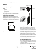
Standard Mounting 180° adjustable mounting brackets supplied (two sets 445L-AF6143)
Weight Varies by protective height
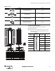
Housing Cross Section
Slim profile (standard): 15 mm x 20 mm (0.59 x 0.79 in.)
Reinforced profile (special): 30 mm x 40 mm (1.18 x 1.57 in.)
Optical Window Polycarbonate
Enclosure Treatment Polyester powder coated, silicon free
Connection Type Transmitter/receiver: 8-pin M12 micro QD
Cable Length
1, 2, 3, 5, and 8 m (3.3, 6.6, 9.8, 16.4, and 26.2 ft) cable M12 to RJ45 for MSR41 or MSR42.
Max. total system length can not exceed 10 m (32.8 ft).
Patchcords
1, 3, and 5 m (3.3, 9.8, and 16.4 ft) M12 to M12 patchcords.
Total system length cannot exceed 10 m (32.8 ft) including protective height of Micro 400, integrated cables and patchcords from M12
connector to MSR41 or MSR42.