
User Manual Manual
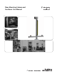

Floor Mounting Stand and Cantilever User Manual
6
Original instructions
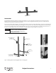
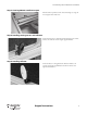
Step 6: Mount cover profiles
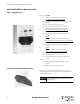
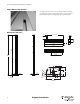
Dimensions [mm (in.)]
Run cables in the slots once the system is complete. Finish the assembly by
positioning the profile covers. Using a rubber mallet or a block of material
that will not damage the material, lightly tap the cover profiles in place.
60
(2.36)
12
(0.47)
2015
(79.3)
2000
(78.7)
60
(2.36)
20 (0.79)
dened at installation
80
(3.15)
500 (19.69)
503 (19.80)
9.4
(0.37)
60
(2.36)
60
(2.36)
40
(1.57)
300 (11.81)
cover for cable
locate appropriately
24 (0.94)
30 (1.18)
3 x M12
R 5.50 (0.22)
10°
14
(0.55)
R 105 (4.13)
30
(1.18)
30 (1.18)
150
(5.91)
100
(3.94)
240 (9.45)
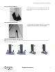
Base Plate