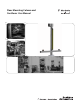
Floor Mounting Column and Cantilever User Manual
Important User Information Because of the variety of uses for the products described in this publication, those responsible for the application and use of this control equipment must satisfy themselves that all necessary steps have been taken to assure that each application and use meets all performance and safety requirements, including any applicable laws, regulations, codes and standards.
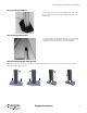
Introduction The Allen-Bradley Guardmaster aluminum mounting stand is offered in a two meter length and is supplied with a floor mounting plate and the hardware necessary to mount the floor plate to the aluminum extrusion as well as leveling hardware for the floor plate. The two meter aluminum extrusion has a cross section of 60 x 60 mm (2.36 x 2.36 in.). The two meter mounting stand is designed for mounting safety light curtains, corner mirrors, and the 445L muting box.
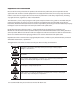
Floor Mounting Stand and Cantilever User Manual 445L-AMSTD2M Floor Mounting Stand Step 1: Supplied parts Pos Qty Description 1 Profile 60 x 60 x 2000 mm (2.4 x 2.4 x 78.7 in.) 1 pc. 2 Floor plate to extrusion mounting hardware 4 pcs. Zinc hexagon socket head cap screws DIN 912 M6 x 25 mm (0.98 in.) 6 pcs. Zinc washer (flat) M6 x 12 mm (0.47 in.) 8 3 pcs. Zinc set screw DIN 913 M12 x 12 mm (0.47 in.) 4 1 pc.
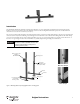
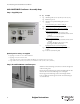
Floor Mounting Stand and Cantilever User Manual Step 3: Leveling hardware Three hexagon socket head cap screws are supplied to level the floor plate. If necessary, premount these screws before attaching the floor plate to the aluminum post. Step 4: Install profile covers Four 300 mm profile covers are supplied with each two meter post to hide the cables. Install these after the cables are assembled and connected. Use a rubber mallet to secure these profile covers to the two meter post.
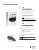
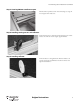
Floor Mounting Stand and Cantilever User Manual 445L-AMSTDMUT Cantilever—Assembly Steps Step 1: Supplied parts Pos Qty Description 1 1 pc. Aluminum profile 60 x 60 x 500 mm (2.4 x 2.4 x 19.7 in.) 1 pc. Black end cap 60 x 60 1 pc. Aluminum cover profiles for hiding cables (300 mm (11.8 in.)) 2 1 3 To attach cantilever post to the floor stand post 4 pcs. Stainless steel universal fastening set #6 (item no. 0044174) 2 4 4 5 3 6 8 7 6 1 pc.
Floor Mounting Stand and Cantilever User Manual Step 3: Securing 500 mm cantilever to post Hold the cantilever profile between the universal fastening sets. Using a #4 hex tool tighten the hex head screws. Step 4: Installing muting sensors and reflectors Mount the muting sensor to the bracket. Mount the muting sensor and the bracket to the slot in the extrusion using the supplied hardware. Step 5: Installing reflector Mount the reflector to the supplied bracket.
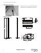
Floor Mounting Stand and Cantilever User Manual Step 6: Mount cover profiles Run cables in the slots once the system is complete. Finish the assembly by positioning the profile covers. Using a rubber mallet or a block of material that will not damage the material, lightly tap the cover profiles in place. Dimensions [mm (in.)] 20 (0.79) defined at installation 40 (1.57) 80 (3.15) 60 (2.36) 60 (2.36) 500 (19.69) 9.4 (0.37) 503 (19.80) 2000 (78.7) 300 (11.
Floor Mounting Stand and Cantilever User Manual Original instructions 7
Floor Mounting Stand and Cantilever User Manual 8 Original instructions
Floor Mounting Stand and Cantilever User Manual Original instructions 9
GuardShield is a trademark of Rockwell Automation, Inc. www.rockwellautomation.com Power, Control and Information Solutions Headquarters Americas: Rockwell Automation, 1201 South Second Street, Milwaukee, WI 53204 USA, Tel: (1) 414.382.2000, Fax: (1) 414.382.