
Safety Laser Scanner User Manual Instruction Manual

60 Rockwell Automation Publication 10000337275 Ver 01—October 2014
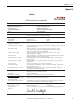
Chapter 12 Technical specifications
Applies to the voltage range between V
S
and 0 V.
Switching currents up to 500 mA are allowed briefly (100 ms).
In the case of a fault (0 V cable open circuit) maximally the leakage current flows in the OSSD cable. The downstream controller must
detect this status as LOW. An FPLC (fail-safe programmable logic controller) must be able to identify this status.
Make sure to limit the individual line core resistance to the downstream controller to this value to ensure that a cross-circuit between
the outputs is safely detected. (Also note EN 60 2041.)
When active, the outputs are tested cyclically (brief LOW). When selecting the downstream controllers, make sure that the test
signals do not result in deactivation.
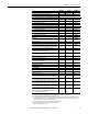
Minimum Typical Maximum
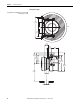
Electrical connection Connecting cable with round plug connector
Cable length for power supply tolerance ±10% [m (ft)] 25 (82.0)
Cable length for power supply tolerance ±5% [m (ft)] 34 (111.5)
Cable length for power supply tolerance ±1% [m (ft)] 40 (131.2)
Universal I/Os
Input resistance when HIGH 2 kΩ
Voltage for HIGH 11 V 24 V 30 V
Voltage for LOW –3V 0 V 5 V
Input capacitance 15 nF
Static input current 6 mA 15 mA
Actuating time of the control switch for restart 120 ms 200 ms
HIGH switching voltage at 100 mA V
S
– 3.3 V V
S
Source switching current 100 mA 200 mA
Current limiting (after 5 ms at 25 °C) 600 mA 920 mA
Power up delay 1.4 ms 2 ms
Switch off delay 0.7 ms 2 ms
Response time with configuration as second warning field output Corresponds to the resulting response time of the
OSSDs plus 50 ms
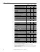
OSSDs
Output signal switching device pair 2 PNP semiconductors, short-circuit protected ,
cross-circuit monitored
HIGH switching voltage at 250 mA V
S
– 2.7 V V
S
Switching voltage LOW 0 V 0 V 2 V
Source switching current 6 mA 250 mA
Leakage current
250 A
Load inductance 2.2 H
Load capacity 2.2 F at 50 Ω
Switching sequence (without switching) 5 ¹/s
Permissible cable resistance
2.5 Ω
Test pulse width
230 s 300 s
Test frequency 120 ms
Power-up delay of the OSSDs from red to green 120 ms
Time offset on switching the OSSDs between OSSD2 and OSSD1 2 ms
Configuration and diagnostics interface
Communication protocol RS-232 (proprietary)
Transmission speed 38400 Baud
Cable length at 38400 Baud and 0.25 mm² cables 15 m (49 ft)
Galvanic isolation No
Output TxD HIGH 5 V 15 V
Output TxD LOW –15 V –5 V
Voltage range RxD –15 V 15 V
Switching threshold RxD LOW –15 V 0.4 V
Switching threshold RxD HIGH 2.4 V 15 V
Short-circuit current at TxD –60 mA 60 mA
Max. voltage level at RxD –15 V 15 V
Max. voltage level at TxD –11 V 11V
11
12
13
11
12
13