
Safety Laser Scanner User Manual Instruction Manual

Rockwell Automation Publication 10000337275 Ver 01—October 2014 41
Chapter 6 Electrical installation
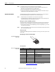
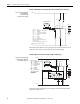
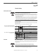
Core assignment of the SafeZone Mini extension cable
Table 10: Core assignment of the
SafeZone Mini cable
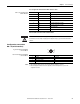
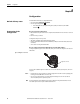
Universal I/O connections of the SafeZone Mini
Do not use the universal I/O connection outputs for safety-related tasks!
The universal I/O connection outputs are purely application diagnostics outputs, e.g. for the transfer of information to
controllers.
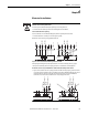
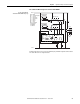
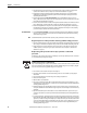
Configuration connection
M8 × 4 (serial interface)
Fig. 39: Pin assignment configuration
connection M8 × 4
Table 11: Pin assignment configuration
connection M8 × 4
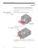
Notes
After configuration always remove the connecting cable from the configuration connection!
After the configuration of the device has been completed, locate the attached protection cap to cover the
configuration connection.
Core Color Function
1
White Output for warning field 1
2
Brown Supply voltage 24V DC
3
Green Universal I/O connection 1
4
Yellow Universal I/O connection 2
5
Gray Output signal switching device OSSD1
6
Pink Output signal switching device OSSD2
7
Blue Supply voltage 0V DC
8
FE/shield Functional earth/shield
ATTENTION
4
1
2
3
Pin SafeZone Mini PC-side RS-232-DSub
1 Reserved Not assigned
2RxD Pin 3
30VDC (voltage supply) Pin5
4TxD Pin2