SafeZone Mini Safety Laser Scanner User Manual R
Important User Information Because of the variety of uses for the products described in this publication, those responsible for the application and use of this control equipment must satisfy themselves that all necessary steps have been taken to assure that each application and use meets all performance and safety requirements, including any applicable laws, regulations, codes and standards.
Contents Contents About this document . . . . . . . . . . . . . . . . . . . . . . . . . . . . . . . . . . . . . . . . . . . . . . . . . . . Chapter 1 Function of this document . . . . . . . . . . . . . . . . . . . . . . . . . . . . . . . . . . . . . . . . . . . . . . . . . . . . . . . . . . . . . . . . . . . . . . . . . . . . . . . 4 Target group . . . . . . . . . . . . . . . . . . . . . . . . . . . . . . . . . . . . . . . . . . . . . . . . . . . . . . . . . . . . . . . . . . . . . . . . . . . . . . . . .
Contents Minimum distance . . . . . . . . . . . . . . . . . . . . . . . . . . . . . . . . . . . . . . . . . . . . . . . . . . . . . . . . . . . . . . . . . . . . . . . . . . . . . . . . 29 Mobile applications . . . . . . . . . . . . . . . . . . . . . . . . . . . . . . . . . . . . . . . . . . . . . . . . . . . . . . . . . . . . . . . . . . . . . . . . . . . . . . . . . . . . 30 Mounting (continued) . . . . . . . . . . . . . . . . . . . . . . . . . . . . . . . . . . . . . . . . . . . . . . . . . .
Contents SafeZone Mini . . . . . . . . . . . . . . . . . . . . . . . . . . . . . . . . . . . . . . . . . . . . . . . . . . . . . . . . . . . . . . . . . . . . . . . . . . . . . . . . . . . . 61 Mounting kits . . . . . . . . . . . . . . . . . . . . . . . . . . . . . . . . . . . . . . . . . . . . . . . . . . . . . . . . . . . . . . . . . . . . . . . . . . . . . . . . . . . . 62 Scan plane origin. . . . . . . . . . . . . . . . . . . . . . . . . . . . . . . . . . . . . . . . . . . . . . . . . . . . . . . . . .
Chapter 1 About this document Chapter 1 About this document Please read this chapter carefully before working with this documentation and the SafeZone Mini. Function of this document These operating instructions are designed to address the technical personnel of the machine manufacturer or the machine operator in regards to correct mounting, electrical installation, commissioning, operation and maintenance of the SafeZone Mini safety laser scanner.
Chapter 1 About this document ESD Electrostatic discharge ESPE Electro-sensitive protective equipment FPLC Fail-safe programmable logic controller OSSD Output signal switching device = signal output of the protective device that is used to stop the dangerous movement RIA Robotic Industries Association SCD software Rockwell Automation Safety Configuration and Diagnostic Software (SCD software) = software for configuration and diagnostics on the SafeZone Mini Symbols used Recommendation Recommendations are
Chapter 2 On safety Chapter 2 On safety This chapter deals with your own safety and the safety of the system operators. Please read this chapter carefully before working with the SafeZone Mini or with the machine protected by the SafeZone Mini. Qualified safety personnel The SafeZone Mini safety laser scanner must be installed, connected, commissioned and serviced only by qualified safety personnel.
Chapter 2 On safety General safety notes and protective measures ATTENTION Pay attention to the safety notes! Please observe the following items in order to ensure the correct use of the SafeZone Mini safety laser scanner. Repair only by authorized persons! The improper repair of the protective device can result in the loss of the protective function. The protective device is only allowed to be repaired by the manufacturer or persons authorized by the manufacturer.
Chapter 2 On safety Disposal Unusable or irreparable devices should always be disposed as per the applicable national regulations on waste disposal (e.g. European waste code 16 02 14). Note • Information on the individual materials in the SafeZone Mini is given in Chapter 12 “Technical specifications” on page 55. Separation of materials ATTENTION Only qualified safety personnel are allowed to separate materials! Caution is required when dismantling devices. There is a risk of injuries.
Chapter 2 On safety Regional standards, for example: • Performance Criteria for Safeguarding (ANSI B11.19) • Machine tools for manufacturing systems/cells (ANSI B11.20) • Safety requirements for Industrial Robots and Robot Systems (ANSI/RIA R15.06) • Safety Standard for guided industrial vehicles and automated functions of named industrial vehicles (ANSI B56.5) Note To some extent these standards require the protective device to have the safety level “Control reliable.
Chapter 3 Product description Chapter 3 Product description This chapter provides information on the special features and properties of the SafeZone Mini safety laser scanner. It describes the construction and the operating principle of the device. Special features • • • • • • • • • • • • • Function The SafeZone Mini safety laser scanner operates correctly as a protective device only if the following conditions are met: • The control of the machine, system or vehicle must be electrical.
Chapter 3 Product description The SafeZone Mini works on the principle of time-of-flight measurement. It sends out very short pulses of infrared light (send pulses). At the same time an “electronic stopwatch” is started. When the light hits an object, it is reflected and received by the safety laser scanner (receive pulses). From the time between sending and reception (t) the SafeZone Mini calculates the distance to the object. Fig.
Chapter 3 Product description Note A warning field on the SafeZone Mini is not allowed to be used for tasks related to the protection of people. Contour monitoring In addition to the protective field, the SafeZone Mini can also monitor a contour (e.g. the floor in vertical applications).
Chapter 3 Product description Applications Table 2: Possible applications for the SafeZone Mini SafeZone Mini: Hazardous area protection on an insertion station SafeZone Mini: Hazardous point protection on an insertion station SafeZone Mini: Presence detection for a safety light curtain SafeZone Mini: Protection of an automated guided vehicle (AGV) for one velocity Access protection for high areas of access Rockwell Automation Publication 10000337275 Ver 01—October 2014 13
Chapter 3 Product description Status indicators LEDs and sevensegment display The LEDs and the sevensegment display indicate the operational status of the SafeZone Mini. They are on the front face of the safety laser scanner. Fig. 6: Status indicators on the SafeZone Mini The symbols have the following meaning: Table 3: Status indicators on the SafeZone Mini Symbol SafeZone Mini OSSDs in the OFF state (e.g.
Chapter 4 Configurable functions Chapter 4 Configurable functions System parameters A name can be assigned to the application configured as well as to the safety laser scanner(s). The names are saved in the devices after the configuration is transferred. The name chosen may be, for example, the identifier for the vehicle, system or the machine. You enter the application name and the names of the safety laser scanners used in the SCD software. Application name Enter a name for your application.
Chapter 4 Configurable functions Application With the help of the SCD software you can configure the SafeZone Mini for the required application. Depending on whether you select a stationary or a mobile application, different configuration options are available: Table 4: Comparison of mobile and stationary applications Mobile applications [mm (in.)] Stationary applications [mm (in.)] Resolution • 30 (1.2) (hand detection with smaller protective field • 30 (1.
Chapter 4 Configurable functions Universal I/O connections of the SafeZone Mini ATTENTION You are not allowed to use the universal I/O connections for safety-relevant functions! You are only allowed to use the universal I/O connections for signaling. You must never use the signals for controlling the application or for safety-relevant functions. The SafeZone Mini has two universal I/O connections (see Chapter 6, “Round plug connector SafeZone Mini” on page 40).
Chapter 4 Configurable functions OSSDs Internal OSSDs of the SafeZone Mini If there is an object in the protective field, the internal OSSDs on the SafeZone Mini always switch. This can not be configured differently in the SCD software. External device monitoring (EDM) SafeZone Mini The EDM checks if the contactors actually de-energize when the protective device is tripped.
Chapter 4 Configurable functions Configuration of the SafeZone Mini with restart interlock Fig. 8: Schematic outline of the operation with restart interlock Note Do not confuse the restart interlock with the starting interlock on the machine. The starting interlock prevents the machine starting after switching on. The restart interlock prevents the machine starting again after an error or a protective field infringement.
Chapter 4 Configurable functions Field sets Configuring the protective field and warning field With the aid of the SCD software you can configure the field set, which comprises a protective field and two warning fields . During this process you configure the shape and size of the protective and warning fields. You can realize any field shape required. Fig. 9: Creating a field set in the SCD software Note The area to be monitored is scanned radially by the SafeZone Mini.
Chapter 4 Configurable functions Protective field or warning field suggested by the safety laser scanner The SCD software can suggest the protective field or warning field in the field set editor. The safety laser scanner scans the visible surrounding contour several times. From the data obtained the SCD software suggests the contour and size of the field. The following figure shows an example for the reading of a protective field: Fig.
Chapter 4 Configurable functions The OSSDs on the SafeZone Mini change to the OFF state or the SafeZone Mini Remote signals if … • There is an object in the protective field. • The monitored surrounding contour is no longer in the tolerance band (e.g. if the position of the SafeZone Mini is changed). Notes • You can define any number of contour segments. • The contour segments must not be narrower than the configured resolution.
Chapter 4 Configurable functions Multiple sampling If multiple sampling is set, an object must be scanned several times before the SafeZone Mini switches its OSSDs to the OFF state. In this way you can reduce the probability that insects, welding sparks or other particles result in the shutdown of the system. If a multiple sampling of three is configured, for instance, an object must be detected in the protective field three times in succession before the SafeZone Mini switches the OSSDs to the OFF state.
Chapter 5 Mounting Chapter 5 Mounting This chapter describes the preparation and completion of the mounting of the SafeZone Mini safety laser scanner.
Chapter 5 Mounting For a horizontal stationary application determine … • The protective field size to observe the necessary minimum distance. • The height of the scan plane. • The restart behavior. • Measures to protect any areas not covered by the SafeZone Mini. Note Once you have defined the protective field size, mark the boundaries of the protective field on the floor.
Chapter 5 Mounting Response time TS of the SafeZone Mini The response time TS of the SafeZone Mini depends on … • The basic response time of the SafeZone Mini. • The multiple sampling set. See Chapter 12 “OSSD response times” on page 55. Supplement ZR for measurement errors caused by reflection ATTENTION Avoid mounting retroreflectors at a distance of less than one meter from the boundary of the protective field! With retroreflectors positioned at a distance of less than 1 m (39.4 in.
Chapter 5 Mounting How to calculate the supplement C: If there is enough empty space in front of your machine or system, use 1200 mm (47.2 in.) for the supplement C. If the minimum distance is to be kept as small as possible, calculate C using the following formula: C = 1200 mm – (0.4 × HD) Here HD is the height at which the protective field is mounted. Note The minimum supplement C to prevent reaching over is 850 mm (33.5 in.)(arm length). Height of the scan plane at 70 mm (2.8 in.
Chapter 5 Mounting Fig. 18: Access protection Protective field Contour of the floor as reference S The minimum distance S as defined in EN ISO 13855 and EN ISO 13857 depends on: • Reach or approach speed • Stopping/run-down time of the machine or system (The stopping/run-down time is shown in the machine documentation or must be determined by taking a measurement.
Chapter 5 Stationary vertical operation for hazardous point protection Mounting Hazardous point protection is necessary if the operator must remain near the dangerous state of the machine. Hand protection is required for hazardous point protection. Note The SafeZone Mini must therefore be configured with a resolution of at least 40 mm (1.6 in.) ATTENTION Never use the SafeZone Mini for safety applications in which finger protection is required! Due to the finest possible resolution of 30 mm (1.2 in.
Chapter 5 Mounting Note The reach/approach speed is already included in the formula. If the result S is 500 mm (19.7 in.), then use the determined value as the minimum distance. If the result S is > 500 mm (19.7 in.), you may be able to reduce the minimum distance using the following calculation: S = 1600 × (TM + TS) + 8 × (d – 14) [mm] If the new value S is > 500 mm (19.7 in.), then use the newly calculated value as the minimum distance. If the new value S is 500 mm (19.7 in.
Chapter 5 Fig. 20: Stopping distance Mounting SafeZone Mini SAnF SAnS SBr Note Take into account that the braking distance for a vehicle is not linear with increasing velocity, but increases in a square function. Fig.
Chapter 5 Mounting Supplement ZR for measurement errors caused by reflection With retroreflectors in the background at a distance of less than 1 m (39.4 in.) from the boundary of the protective field, the supplement ZR is 200 mm (7.87 in.). Supplement ZF due to lack of ground clearance This supplement is necessary because a person is generally detected above the foot and the braking action can therefore not take into account the length of the foot in front of the detection point.
Chapter 5 Mounting Height of the scan plane ATTENTION Mount the SafeZone Mini such that the scan plane is at a maximum height of 200 mm (7.87 in.)! In this way also persons lying down will be reliably detected. Tilting the protective field so that objects with a diameter of 200 mm (7.87 in.)are not detected, is not allowed. We recommend aligning the scan plane horizontally at 70 mm (2.76 in.) Fig. 24: Mounting height [mm (in.)] Set protective field length 190 (7.48) 150 (5.
Chapter 5 Mounting Fig. 26: Preventing unprotected areas Mount the SafeZone Mini for example on a corner to prevent unprotected areas. Fig.
Chapter 5 Mounting Near range Make the near range impassible using a bar or a recess, or additionally protect the near range (50 mm (2.0 in.)) wide area in front of the optics cover) using a proximity switch with 50 mm (2.0 in.) acquisition range. The vehicle may then be accelerated as required. Mounting steps ATTENTION Only qualified safety personnel are allowed to separate materials! Caution is required when dismantling devices. There is a risk of injuries.
Chapter 5 Mounting Direct mounting The SafeZone Mini has two threaded holes M5×8 on the rear. Using them you can mount the SafeZone Mini directly on the intended mounting surface. To avoid a possible tendency to vibrate, if necessary the reference surface on the rear can be used as the third mounting point . Fig. 30: Direct mounting M5 x 8 Notes During mounting, please observe the dimensional drawings in Chapter 12, “Dimensions” on page 61.
Chapter 5 Fig. 32: Mounting with mounting kit 2 Mounting kit 1 Mounting kit 3 Mounting Mounting kit 4 Mounting screws Centering pin Mounting screws Threaded holes M4 Mount mounting kit 1 or 2 to the SafeZone Mini. Mount the mounting kit 4 on the mounting surface. Fit the centering pin [4 mm (0.16 in.)] in the central hole on mounting bracket 4. Fit mounting kit 3 to mounting kit 4 and mount it using two fixing screws M4 ×10.
Chapter 5 Mounting Fig. 35: Mounting on a cross Min. 3° Fig. 36: Reverse mounting, parallel offset Min. 100 mm (3.94 in.) Fig. 37: Reverse mounting of two SafeZone Mini, with parallel offset Min. 100 mm (3.94 in.
Chapter 6 Electrical installation Chapter 6 Electrical installation ATTENTION Switch the entire machine/system off line! The machine/system could unintentionally start up while you are connecting the devices. Ensure that the entire machine/system is disconnected during the electrical installation. Connect OSSD1 and OSSD2 separately! You are not allowed to connect OSSD1 and OSSD2 together, otherwise signal safety will not be ensured.
Chapter 6 Electrical installation Notes Route all cables and connection cables such that they are protected from damage. Ensure that also the controller connected and all devices related to safety have the required category as per EN ISO 138491 or the required performance level as per EN ISO 138491! If you use screened cables, lay the screen evenly around the connection terminal. Ensure that the SafeZone Mini is adequately protected electrically.
Chapter 6 Electrical installation Core assignment of the SafeZone Mini extension cable Table 10: Core assignment of the SafeZone Mini cable Core 1 Color White Function Output for warning field 1 2 Brown Supply voltage 24V DC 3 Green Universal I/O connection 1 4 Yellow Universal I/O connection 2 5 Gray Output signal switching device OSSD1 6 Pink Output signal switching device OSSD2 7 Blue Supply voltage 0V DC 8 FE/shield Functional earth/shield Universal I/O connections of the Saf
Chapter 7 Application examples and connection diagrams Chapter 7 Application examples and connection diagrams The examples shown are only provided as an aid for your planning. You may need to consider additional protection measures for your application. Stationary applications Applications with one monitored area (SafeZone Mini) Fig.
Chapter 7 Mobile applications Application examples and connection diagrams Vehicle monitoring for unidirectional travel (SafeZone Mini) Fig. 42: Vehicle monitoring with SafeZone Mini SafeZone Mini with one protective field and two warning fields The SafeZone Mini monitors the area in the direction of travel and switches its OSSDs to the OFF state to stop the vehicle as soon as there is an object in the protective field.
Chapter 7 Application examples and connection diagrams SafeZone Mini with restart interlock and external device monitoring Fig.
Application examples and connection diagrams Chapter 7 Two SafeZone Mini safety laser scanners with GSR DI Fig.
Chapter 8 Configuration Chapter 8 Configuration Default delivery status The SafeZone Mini is delivered in a non-configured default state. • The operational status is Waiting for configuration. • The sevensegment display indicates . . – On the SafeZone Mini the output signal switching devices (OSSDs) are in the OFF state, the red LED is illuminated: Preparation of the configuration .
Chapter 9 Commissioning Chapter 9 Commissioning Initial commissioning ATTENTION Commissioning requires a thorough check by qualified safety personnel! Before you operate a system protected by the SafeZone Mini safety laser scanner for the first time, make sure that the system is first checked and released by qualified safety personnel. The result of the test must be documented. Please read the notes in Chapter 2, “On safety” on page 6.
Chapter 9 Commissioning Check the effectiveness of the protective device mounted to the machine, using all selectable operating modes as specified in the checklist in the annex (see Chapter 14, “Checklist for the manufacturer” on page 70). Ensure that the operating personnel of the machine protected by the safety laser scanner are correctly instructed by qualified safety personnel before being allowed to operate the machine.
Chapter 10 Maintenance and care Chapter 10 Maintenance and care ATTENTION Do not make any repairs to the device! The SafeZone Mini does not contain any repairable components. For this reason do not open the SafeZone Mini components and only replace the parts that are described in the following chapters as replaceable. Switch the entire machine/system off line! The system could inadvertently start up while you are replacing the optics cover.
Chapter 10 Maintenance and care How to replace the optics cover: Notes • Only use a new optics cover (see Chapter 13, “Miscellaneous,” on page 65). • • When replacing the optics cover, take ESD protection measures. Set the torque wrench to 1.2 Nm (hand-tight) and have this at hand. Disconnect the round plug connector on the end of the connecting cable and remove the SafeZone Mini. Take the SafeZone Mini to a clean place (office, repair shop or similar).
Chapter 11 Diagnostics Chapter 11 Diagnostics This chapter describes how to identify and remedy errors and malfunctions during the operation of the safety laser scanner. In the event of faults or errors ATTENTION Do not operate if behavior is unclear! Stop the machine, the system or the vehicle if you cannot clearly identify or allocate an error and if you cannot safely remedy the malfunction.
Chapter 11 Diagnostics Error and status indications on the LEDs This section describes the meaning of the error and status indications of the LEDs and how you can respond. You will find a description of the indicators in Chapter 3, “Status indicators” on page 14, the connections for the outputs of the SafeZone Mini in Chapter 6, “System connection” on page 40.
Chapter 11 Table 15: Error and status indications on the sevensegment display Display . Possible cause Power-up cycle — all segments are activated sequentially. Object in protective field . or . . Object in warning field 2 No error Initialization of the device The display goes out automatically when the SafeZone Mini has been initialized and/or the connection to the second device has been made. If the display . does not go off: Check whether the partner device is in operation.
Chapter 11 Diagnostics Short-circuit between OSSD connection 1 and 2 General OSSD wiring error Check the wiring and rectify the error. Check the complete wiring of the OSSDs. The SafeZone Mini is receiving For the correct function of the safety laser scanner, always ensure that measured values are received within no measured values within a a range of 90°; this range can be moved as required range of at least 90° within the scan range. (measuring range maximum 29.9 m(98.
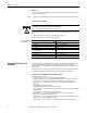
Chapter 12 Technical specifications Chapter 12 Fig. 48: Diagram scanning range 2 meter SafeZone Mini Remission (%) Technical specifications Reflectors > 2000% Reflective films > 300% 500 200 White plaster Writing paper 100 50 Grey cardboard 20 10 5 Matte black paint 2 Black shoe leather 1 0.1 0.2 0.5 1 2 5 10 20 50 Scanning range [m] Fig.
Chapter 12 Technical specifications How to calculate the total response time TS: TS = tB + TMFA + Where … tB = Basic response time = 80 ms TMFA = Supplement due to multiple sampling > 2 Multiple sampling On the SafeZone Mini at least double multiple sampling is always set. For a multiple sampling of three or higher you must add a supplement of 80 ms to the basic response time.
Chapter 12 Technical specifications After a further half basic response time of the SafeZone Mini there is a shut-down test , 120 ms later a further voltage test . Then the SafeZone Mini performs a shut-down test and a voltage test alternately at an interval of 120 ms. Fig. 51, Fig. 52 and Fig. 53 show the pulse duration for the individual tests. Fig. 51: Voltage test after switching on the OSSDs Approx. 650 s OSSD1 <300 s <300 s OSSD2 Fig. 52: Shut-down test Approx.
Chapter 12 Technical specifications Data sheet Table 17: Data sheet SafeZone Mini Minimum General data Type Safety Integrity Level SIL claim limit Category Performance Level PFHd (mean probability of a dangerous failure per hour) TM (mission time) Laser protection class Enclosure rating Protection class Operating temperature range Storage temperature range Typical Maximum 3 (EN 614961) SIL2 (IEC 61508) SILCL2 (EN 62061) Category 3 (EN ISO 138491) PL d (EN ISO 138491) 8 × 10⁻⁸ 20 years (EN IS
Chapter 12 Technical specifications Minimum Typical Maximum Functional data Resolution of the 2 m SafeZone Mini [mm (in.)] 30, 40, 50, 70 (1.2, 1.6, 2.0, 2.8) Resolution of the 3 m SafeZone Mini [mm (in.)] 30, 40, 50, 70, 150 (1.2, 1.6, 2.0, 2.8, 5.9) Protective field of the 2 m SafeZone Mini Medium Range [m (ft)] At 30 mm (1.2 in.) resolution 1.25 (4.10) At 40 mm (1.6 in.) resolution 1.60 (5.25) At 50 mm (2.0 in.) resolution 2.00 (6.56) At 70 mm (2.8 in.) resolution 2.00 (6.
Chapter 12 Technical specifications Electrical connection Cable length for power supply tolerance ±10% [m (ft)] Cable length for power supply tolerance ±5% [m (ft)] Cable length for power supply tolerance ±1% [m (ft)] Universal I/Os Input resistance when HIGH Voltage for HIGH Voltage for LOW Input capacitance Static input current Actuating time of the control switch for restart HIGH switching voltage at 100 mA Minimum Typical Maximum Connecting cable with round plug connector 25 (82.0) 34 (111.
Chapter 12 Dimensions [mm (in.)] Technical specifications SafeZone Mini Fig. 54: Dimensional drawing SafeZone Mini 94 (3.7) dia. 116 (4.57) 79.7 (3.14) 43.3 (1.70) 36.5 (1.44) 73 (2.87) dia. 102 (4.02) dia. 200 (7.87) max. 104 (4.09) 54.5 (2.15) 23.8 (0.94) Min. 15 Min. 15 36.4 (1.43) 10.5 (0.41) M5 x 7.5 43.3 (1.70) 5 (0.20) 250 (9.
Chapter 12 Technical specifications Mounting kits Fig. 55: Dimensional drawing, mounting kit 1 442L-AMBSZMN1 73 (2.87) 4 (0.16) DIN74-F5 110 (4.33) 15.9 (0.63) 16 (0.63) 49 (1.93) 74.7 (2.94) 21.9 (0.86) Fig. 56: Dimensional drawing, mounting kit 2 442L-AMBSZMN2 21.9 (0.86) 37.9 (1.49) 100 (3.94) dia 109.6 (4.31) 102.5 (4.03) 48 (1.89) 4 (0.16) 73 (2.87) 78 (3.07) 110 (4.33) DIN74-F5 15.9 (0.63) 49 (1.93) 74.7 (2.94) 16 (0.63) 15.7 (0.62) 21.9 (0.86) Fig.
Chapter 12 Technical specifications Fig. 58: Dimensional drawing, mounting kit 4 442L-AMBSZMN4 8.8 15 ) .91 5 0( 15 ) 25 (6. ) .12 5 0( 13 41 (1.57) 5 (0.20) M4 20.5 (0.80) 5.5 (0.
Chapter 12 Technical specifications Scan plane origin Fig. 59: Dimensional drawing of the scan plane with mounting kit 1, 3, and 4 150 (5.91) 73 (2.87) 270° 130 (5.12) 23.8 (0.94) 36.4 (1.43) 74.7 (2.94) 69.7 (2.74) 43.3 (1.70) 54.5 (2.15) 59.7 (2.35) 104 (4.09) 109.6 (4.31) 74.7 (2.94) Min. 15 Min.
Chapter 13 Items supplied for SafeZone Mini Chapter 13 Items supplied for SafeZone Mini • Safety laser scanner • Operating instructions and SCD software on CDROM • Adhesive label Important information Note Cordsets for the SafeZone mini not included.
Chapter 13 66 Items supplied for SafeZone Mini 442L-AMBSZMN4 442L-AMBSZMN4 SafeZone mini mounting bracket 3 442L-SZMNW 442L-SZMNW SafeZone mini replacement window kit 442L-ACUSB-2 2 m (6.6 ft) USB programming cable 442L-ACUSB-10 10 m (32.
Chapter 14 Annex Chapter 14 Annex EU Declaration of Conformity Identification of the product: Safezone Safety Laser Scanner Name and address of the manufacturer: Name and address of the authorised representative: Rockwell Automation, Inc. Rockwell Automation B.V. 2 Executive Drive Rivium Promenade 160 Chelmsford, MA 01824 2909 LM Capelle aan den Ijssel USA The Netherlands This declaration of conformity is issued under the sole responsibility of the manufacturer.
Chapter 14 Annex Catalogue number Series 1 Description 442L-SFZNSZ Safezone single-zone safety laser scanner 442L-SFZNMZ Safezone multi-zone safety laser scanner 442L-SFZNMN Safezone mini safety laser scanner 442L-SFZNMN3 Safezone mini safety laser scanner 1) If no series number is given, then all series are covered. 2) Yes = Product is certified to this directive.
Chapter 14 Rockwell Automation Publication 10000337275 Ver 01—October 2014 Annex 69
Chapter 14 Annex Checklist for the manufacturer Checklist for the manufacturer/installer for installing electro-sensitive protective equipment (ESPE) Details about the points listed below must be present at least during initial commissioning — they are, however, dependent on the respective application, the specifcations of which are to be controlled by the manufacturer/installer.
Chapter 14 Annex Glossary AOPDDR Active opto-electronic protective device responsive to diffuse reflection (e.g. SafeZone Mini, see also CLC/TS 614963) External device monitoring (EDM) A device that electronically monitors the relay or contactor operated by the protective device prior to each new start. Field set Protective fields and warning fields form the so-called field set. Optics cover Plastic part with window for light output. The optics cover is available as a spare part.
Chapter 14 Annex List of tables Table 1: Overview on disposal by components . . . . . . . . . . . . . . . . . . . . . . . . . . . . . . . . . . . . . . . . . . . . . . . . . . . . 8 Table 2: Possible applications for the SafeZone Mini. . . . . . . . . . . . . . . . . . . . . . . . . . . . . . . . . . . . . . . . . . . . . . . 13 Table 3: Status indicators on the SafeZone Mini . . . . . . . . . . . . . . . . . . . . . . . . . . . . . . . . . . . . . . . . . . . . . . . . . .
Chapter 14 List of illustrations Annex Fig. 1: Principle of operation, time-of-flight measurement by the SafeZone Mini . . . . . . . . . . . . . . . . . . . . . . 10 Fig. 2: Principle of operation, rotation of the SafeZone Mini. . . . . . . . . . . . . . . . . . . . . . . . . . . . . . . . . . . . . . . . . 11 Fig. 3: Field set with one protective field and two warning fields . . . . . . . . . . . . . . . . . . . . . . . . . . . . . . . . . . . . 11 Fig. 4: Device components. . . . . . . . . . . . . . .
Chapter 14 Annex Fig. 45: SafeZone Mini in combination with a GSR DI safety relay . . . . . . . . . . . . . . . . . . . . . . . . . . . . . . . . . . . . 45 Fig. 46: Configuration connection. . . . . . . . . . . . . . . . . . . . . . . . . . . . . . . . . . . . . . . . . . . . . . . . . . . . . . . . . . . . . . . 46 Fig. 47: Undo the mounting screws for the optics cover . . . . . . . . . . . . . . . . . . . . . . . . . . . . . . . . . . . . . . . . . . . . 50 Fig.
Chapter 14 Rockwell Automation Publication 10000337275 Ver 01—October 2014 Annex 75
Chapter 14 76 Annex Rockwell Automation Publication 10000337275 Ver 01—October 2014
Chapter 14 Rockwell Automation Publication 10000337275 Ver 01—October 2014 Annex 77
Rockwell Automation maintains current product environmental information on its website at http://www.rockwellautomation.com/rockwellautomation/about-us/sustainability-ethics/product-environmental-compliance.page Allen-Bradley and Rockwell Automation are trademarks of Rockwell Automation, Inc. Trademarks not belonging to Rockwell Automation are property of their respective companies. www.rockwel lautomation.