
Safety Sensor User Manual User Manual


Rockwell Automation Publication 10000202762 Ver 00 - January 2012 49
Chapter 11 Technical specifications
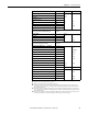
Table 15 - Data sheet SC300
Applies to the voltage range between U
V
and 0 V.
Switching currents ≤500 mA are allowed briefly (100 ms).
In the case of a fault (0V cable open circuit) the maximum leakage current flowing in the OSSD cable. The
downstream controller must detect this status as LOW. A safe PLC (Programmable Logic Controller) must be
able to identify this status.
Make sure to limit the individual cable resistance to the downstream controller to this value to ensure that a
cross-circuit between the outputs is safely detected. (Also note EN 60 204 Electrical Machine Equipment, Part 1:
General Requirements.)
When active, the outputs are tested cyclically (brief LOW). When selecting the downstream controllers, make
sure that the test pulses do not result in deactivation when using the above parameters.
Minimum Typical Maximum
Reset/restart input (RESTART)
Resistance HIGH 2 k Ω
Capacitance 15 nF
Voltage (IEC 61 1312)
HIGH 11 V 24 V 30 V
LOW –3V 0V 5V
Static current 6 mA 15 mA
Actuating time control switch input 120 ms
Teach-in/synchronization (TEACH/SYNCH) input
The input must be operated by a key-operated switch
(contact).
Resistance HIGH 2 k Ω
Capacitance 15 nF
Voltage HIGH 11 V 24 V 30 V
Static current 6 mA 15 mA
Output signal switching devices (OSSDs)
2 PNP semiconductors, short-circuit protected, cross-circuit
monitored
Switching voltage HIGH (active, U
rms
) at 250 mA V
S
–2.7V V
S
Switching voltage LOW (inactive) 0 V 0 V 3.5 V
Source switching current 6 mA 250 mA
Leakage current 250 μA
Load inductance 2.2 H
Load capacity at 50 W 2.2 μF
Permissible line resistance between device and load 2.5 Ω
Test pulse date
Test pulse width 230 μs 300 μs
Test frequency 120 ms
Response time 20 ms
Switch off time 100 ms
Power-up delay of the OSSDs from red to green 30 ms
Contactors
Permissible dropout time 300 ms
Permissible pick-up time 300 ms