
Safety Sensor User Manual User Manual

28 Rockwell Automation Publication 10000202762 Ver 00 - January 2012
Chapter 5 Electrical installation
• To meet the requirements of the relevant product standards (e.g. EN 61 4961), the
external voltage supply for the devices (SELV) must be able to bridge a brief mains
failure of 20 ms. Power supplies according to EN 60 2041 satisfy this requirement.
Suitable power supplies are available as accessories from Rockwell Automation (see
“Accessories” section on page 53).
• Dimension the electrical protection for the camera to suit the information in the
“Data sheet” section on page 47.
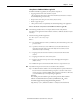
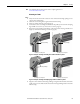
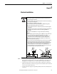
System connection M12 × 8
Figure 20 - System connection SC300
The SC300 has a hard-wired connector cable (length: approx. 30 cm) with a cable plug
M12 × 8.
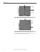
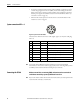
Table 9 - Pin assignment system connection SC300
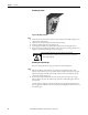
Note Connecting cables of different length are available as accessories from Rockwell
Automation (see “Accessories” section on page 53). If you use connecting cables you have
assembled yourself, ensure the functional earth (pin 8) is connected.
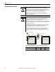
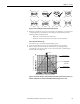
Connecting the SC300
Without external device monitoring (EDM), without internal restart interlock
and without external key-operated pushbutton for teach-in
Note If you use the SC300 without the internal restart interlock, then you must implement the
restart interlock externally, i.e. machine-side.
Pin Color Signal Function
1
White RESTART Reset/restart (optional)
2
Brown +24V DC 24V DC (voltage supply)
3
Green TEACH/SYNC Teach-in/synchronization
4
Yellow EDM External device monitoring (EDM) (optional)
5
Grey OSSD1 OSSD1 (safe output signal switching device 1)
6
Pink OSSD2 OSSD2 (safe output signal switching device 2)
7
Blue GND 0V DC (voltage supply)
8
–FEFunctional earth