
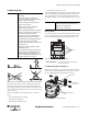
Safety Laser Scanner User guide

R
SafeZone™ Safety Laser Scanner User Manual
32 10000073050, July 2011
Original instructions
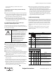
5.1.1 Pin assignments of the I/O modules
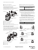
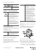
5.2 System connector assembly
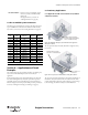
The system plug has holes on the top and rear. Suitable cable glands for
these holes are included with the device.
• One cable gland with M20 cable fitting
• Two blanking plugs for the unused outlets
Note: You can also purchase the SafeZone multizone safety laser scanner
with pre-assembled system connectors (see Section 5.3 “Pre-assembled
system connector” on page 33 and Section 12 “Ordering information” on
page 52).
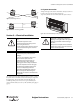
Figure 51: System connector for SafeZone safety laser scanner
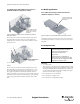
Depending on the application use suitable cable glands on the top or rear.
Use the following cable cross-sections for the individual connections:
Pin Signal Function
SafeZone
Singlezone
SafeZone
Multizone
1
+24V DC Supply voltage SafeZone Multizone
XX
2
0V DC Supply voltage SafeZone Multizone
XX
3
OSSD1 Output signal switching device
XX
4
OSSD2 Output signal switching device
XX
5
RESET Input, reset
XX
6
EDM Input, external device monitoring
XX
7
ERR Application diagnostic output~error/
XX
8
RES_REQ Output, reset required
XX
9
WF Output, object in warning field
XX
10
A1 Static control input A
X
11
A2 Static control input A
X
12
B1 Static control input B
X
13
B2 Static control input B
X
14
Reserved—Do not use
15
Reserved—Do not use
16
+24V DC
Supply voltage output
17
GND
18
Reserved—Do not use
19
Reserved—Do not use
20
+24V DC
Supply voltage output
21
GND
22
Reserved—Do not use
23
Reserved—Do not use
24
25
RxD
RS-422 interface for output of measured
data
26
RxD+
27
TxD+
28
TxD
29
Reserved—Do not use
30
Reserved—Do not use
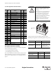
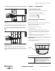
AT TE NTIO N
The length of the spare cable should be such
that the system plug cannot inadvertently be
plugged into a neighboring SafeZone safety
laser scanner.
From experience 20 to 30 cm spare cable at the
scanner have proven to adequate. In this way
you avoid the inadvertent connection of the
system connector to an adjacent SafeZone
safety laser scanner and operation of a SafeZone
safety laser scanner with an incorrect
configuration. The spare cable enables you to
easily change out the SafeZone safety laser
scanner.
Cable Gland
Cable Diameter [mm
Usage
M20 6…12 (0.24…0.47)
• System cables (supply
voltage, outputs, static
M12 (only if supplied) 3…6.5 (0.12…0.26)
• Control switch for
restart or reset
• RS-422 data cables
Cable Recommended Cable Shielded
System cables (supply voltage,
outputs, static input)
9…13 conductors,
0.5…1 mm
2
No
Control switch for restart or reset
2 x 0.25 mm
2
No
RS-422 data cables
4 x 0.25 mm
2
Yes
Cable glands on the
rear
Cable glands on the top