SafeZone Singlezone & Multizone Safety Laser Scanner User Manual R
Important User Information Because of the variety of uses for the products described in this publication, those responsible for the application and use of this control equipment must satisfy themselves that all necessary steps have been taken to assure that each application and use meets all performance and safety requirements, including any applicable laws, regulations, codes and standards.
SafeZone™ Safety Laser Scanner User Manual Related Safety Information You are responsible for the safety of the entire installed control systems and for meeting all applicable laws, codes, and safety requirements.
SafeZone™ Safety Laser Scanner User Manual Table of Contents 1 About This Document . . . . . . . . . . . . . . . . . . . . . . . . . . . . . . . . . . . . . . . . . . . . . . . . . . . . . . . . . . . . . . . . . . . . . . . . . . . . . . . . . . . . . . . . . . . . . . . . 3 1.1 Function of this document . . . . . . . . . . . . . . . . . . . . . . . . . . . . . . . . . . . . . . . . . . . . . . . . . . . . . . . . . . . . . . . . . . . . . . . . . . . . . . . . . . . . . . . . . . . 3 1.2 Target group . .
SafeZone™ Safety Laser Scanner User Manual Section 1 — About this Document Recommendation Please read this section carefully before working with this documentation and the SafeZone safety laser scanner. Users should refer to the Allen-Bradley Guardmaster home page on the Internet at: www.ab.com/safety. Here users will find information on: 1.
SafeZone™ Safety Laser Scanner User Manual 1.6 Symbols used Recommendation Note . Software notes show the location in the SCD software where you can make the appropriate settings and adjustments. In the SCD software on the View menu, Dialog Box, select the item File Cards to go straight to the stated dialog fields. Alternatively, the software wizard will guide you through the appropriate setting.
SafeZone™ Safety Laser Scanner User Manual As a rule these are specialist personnel from the ESPE manufacturer or also those persons who have been appropriately trained at the ESPE manufacturer, are primarily involved in checking ESPE and are allocated the task by the organization operating the ESPE. 2.4 General safety notes and protective measures NOTICE 2.2 Device applications The SafeZone safety laser scanner is used to protect persons and equipment.
SafeZone™ Safety Laser Scanner User Manual • Suitable power supplies are available from Rockwell Automation. The external voltage supply of this device must be capable of buffering brief mains voltage failures of 20 ms as specified in EN 60204. • Machine tools for manufacturing systems/cells (ANSI B11.20) • Included in this document is a checklist for checking by the manufacturer and OEM (see Section 13.1 “Manufacturer’s checklist” on page 54).
SafeZone™ Safety Laser Scanner User Manual • It must be possible to transfer the dangerous state of the machine, the equipment or the vehicle to a safe state at any time using the OSSDs on the SafeZone safety laser scanner after integration in the controller. The SafeZone safety laser scanner uses light pulses precisely radiated in specific directions. Thus the laser scanner does not continuously cover the area to be monitored. In this way resolutions of between 30 mm and 150 mm are achieved.
SafeZone™ Safety Laser Scanner User Manual Protective safety field case 1 Protective safety field case 2 Warning field Figure 4: SafeZone multizone safety laser scanner with two defined monitoring cases on an AGV 3.2.
SafeZone™ Safety Laser Scanner User Manual In this application, the SafeZone safety laser scanner only has a secondary protective function. The primary safety function that stops the dangerous movement is provided in the example by a light curtain , while the SafeZone safety laser scanner monitors the restarting of the machine. Access protection (vertical protection) You can also use the SafeZone safety laser scanner vertically for access protection.
SafeZone™ Safety Laser Scanner User Manual 3.3.3 Other applications (not for personnel protection) Along with safety-related applications, you can also use the SafeZone safety laser scanner for applications in which people do not need to be protected. Protection of an automated guided vehicle AGV In each direction of travel up to four switchable with bi-directional travel field sets 3.
SafeZone™ Safety Laser Scanner User Manual ATTENTION Check the protective safety field configuration. Prior to commissioning the machine or vehicle, check the configuration of the protective safety fields using the instructions in Section 8 “Commissioning” (page 36) and using the checklist (page 54). room contour (less the measurement tolerances).
SafeZone™ Safety Laser Scanner User Manual The maximum protective safety field range is dependent on the resolution selected, and the basic response time for the application is in turn dependent of the protective safety field range. The following tables show the values that can be configured: Table 3: Maximum protective safety field range—SafeZone multizone 5 m range Application 60 ms Basic Response Time 120 ms Basic Response Time Stationary 30 mm (hand detection) 1.90 m 2.
SafeZone™ Safety Laser Scanner User Manual 3.4.4 External device monitoring (EDM) The EDM function monitors the contact elements activated by both the OSSDs (e.g. contactors). The machine is only allowed to start if both contactors are in the de-energized state on reset, that is they are deactivated. The SafeZone safety laser scanner monitors the contactors after every interruption of the protective safety field and before the restart of the machine.
SafeZone™ Safety Laser Scanner User Manual The SafeZone safety laser scanner has a configurable application diagnostic output (device symbol SafeZone safety laser scanner system, context menu Configuration draft, Edit..., file card Scanner name). For the application diagnostic output you must decide Restart delay On the SafeZone safety laser scanner, instead of a restart interlock you can configure a restart delay of 2 to 60 seconds.
SafeZone™ Safety Laser Scanner User Manual If you do not use the restart interlock, leave the inputs disconnected (see Section 5.1.1 “Pin assignments of the I/O modules” on page 32).
SafeZone™ Safety Laser Scanner User Manual IMPORTANT Ensure that the safety distance to the dangerous state is properly established in any monitoring case to protect the hazardous area. IMPORTANT See Section 4 “Installation and mounting” on page 18. It is possible to switch between these monitoring cases during operation using static control inputs. Park mode For mobile applications in which vehicles are parked for a time, the SafeZone multizone safety laser scanner can be switched to park mode.
SafeZone™ Safety Laser Scanner User Manual Input delay If the control device which is used to switch the static control inputs cannot switch within 10 ms (for 60 ms basic response time) or 20 ms (for 120 ms basic response time) to the related input condition (e.g. due to switch bounce times), you must choose an input delay. For the input delay choose the time in which your defined control device can switch to a corresponding input condition.
SafeZone™ Safety Laser Scanner User Manual Warning field interrupted (object in warning field) ATTENTION Front screen contaminated OSSDs deactivated (e.g. if object in the protective safety field, reset necessary, lock-out) No protective function without sufficient safety distance. The SafeZone safety laser scanner’s safety function depends on the system being mounted with the correct safety distance from the hazardous area. OSSDs activated (no object in protective safety field) 3.5.
SafeZone™ Safety Laser Scanner User Manual IMPORTANT • Mount the SafeZone safety laser scanner in a dry place and protect the device from dirt and damage. • Avoid strong electrical fields. These can be produced by welding cables, induction cables in the immediate vicinity and also by mobile telephones operated in close physical proximity. • Ensure that there are no obstacles in the area to be monitored in the field of view of the SafeZone safety laser scanner that could cause interference or shadowing.
SafeZone™ Safety Laser Scanner User Manual IMPORTANT If you are using the SafeZone multizone, you can define several monitoring cases with different protective safety fields. In such cases you must calculate the protective safety field size for all protective safety fields used. You can operate the SafeZone safety laser scanner in stationary horizontal operation with 50 mm or with 70 mm resolution. For each resolution you can choose between 60 ms and 120 ms response time.
SafeZone™ Safety Laser Scanner User Manual Table 9: Advantages and disadvantages of mounting methods Mounting Orientation H D = 875 HD= 0 C = 1200 C = 850 Benefit Disadvantage No external effects due to Scanner low (HS < 300 mm) Inclination of the scanner plane saturation, crawling Larger supplement C Scanner high (HS > 300 mm) Lower protective safety field Inclination of the scanner plane supplement C Danger of crawling beneath (at the front and side) Scanner low (HS < 300 mm) Lower protecti
SafeZone™ Safety Laser Scanner User Manual scanner (Figure 26) and such that standing in an unscanned area is not possible. Table 10: Size of the unprotected areas Size of Unprotected Areas X Y Direct mounting Mounting Method 109 mm 618 mm With mounting kit 1 112 mm 635 mm With mounting kit 1 and 2 127 mm 720 mm With mounting kit 1, 2 and 3 142 mm 805 mm ATTENTION IMPORTANT Prevent crawling beneath the recess by limiting the height of the recess such that nobody can crawl beneath.
SafeZone™ Safety Laser Scanner User Manual The safety distance S as defined in EN 999 and EN 294 depends on: 4.3 Stationary vertical operation for hazardous point protection • Reach or approach speed Hazardous point protection is necessary if the operator must remain near the dangerous state of the machine. Hand protection must be released for hazardous point protection.
SafeZone™ Safety Laser Scanner User Manual If the new value S is ≤ 500 mm, then use 500 mm as the minimum safety distance. Response time of the SafeZone safety laser scanner The response time TS of the SafeZone safety laser scanner depends on • The resolution used • The multiple sampling used See Section 11.2 “OSSD response times” on page 42. 4.4 Mobile applications If the dangerous state is produced by a vehicle (e.g.
SafeZone™ Safety Laser Scanner User Manual You can define different monitoring cases with different protective safety fields. You can switch these using the static control input. Calculate the necessary protective safety field length using the formula: SL = SA + ZG + ZR + ZF + ZB Where...
SafeZone™ Safety Laser Scanner User Manual Vmax Calculation of the protective safety field width: = Response time of the safety laser scanner = Maximum velocity of the vehicle from the related vehicle documentation Calculate the protective safety field width SB using the formula: SB = FB + 2 x (ZG + ZR + ZF) Supplement ZR for measurement error related to reflection Where...
SafeZone™ Safety Laser Scanner User Manual 4.4.4 Methods of preventing unprotected areas When the SafeZone safety laser scanner is mounted on a plane surface, there are areas in front of the mounting surface that are not covered by the safety laser scanner. Figure 37: Fitting the SafeZone safety laser scanner in the vehicle trim Additionally, protect the area near to the scanner (5 cm wide area in front of the front screen) using a proximity switch with 5 cm acquisition range.
SafeZone™ Safety Laser Scanner User Manual t Uv t t U t t UFVz4 t U FV z3 t t U FV z2 UF Figure 38: Advancement for the switch timing • If the input conditions are present at the control inputs within 10 or 20 ms (cf. ), the timing for the switching (tUF) does not need to be advanced. • If an input delay for the control inputs needs to be taken into account (cf. ), the timing for the switching (tUFVz2) must be advanced by the input delay.
SafeZone™ Safety Laser Scanner User Manual 4.6 Mounting steps IMPORTANT • Mounting with mounting kit 1, 2, and 3 Special features to note during mounting: Mount the SafeZone safety laser scanner such that it is protected from moisture, dirt and damage. Ensure that the front screen field of view is not restricted. The mounting kits build one on another. For mounting with kit 2 you will therefore also need kit 1. For fixing with mounting kit 3 you will therefore also need mounting kits 1 and 2.
SafeZone™ Safety Laser Scanner User Manual Mount kit 1 on the mounting surface. Finally mount the SafeZone safety laser scanner on mounting kit 1. Mount the SafeZone safety laser scanner on mounting kit 1. Adjust the SafeZone safety laser scanner longitudinally and cross-wise. 4.6.3 Mounting with mounting kit 2 IMPORTANT With the aid of mounting kit 2 (only in conjunction with mounting kit 1) you can align the SafeZone safety laser scanner in two planes.
SafeZone™ Safety Laser Scanner User Manual 5.1 System connection All input and output connections for the SafeZone safety laser scanner are located on the system connector. This comprises of a 30-pin screw terminal connector and is located in the system connector. 100 mm Figure 48: Mounting on a cross 200 mm Figure 49: Reverse mounting, parallel Section 5 — Electrical Installation ATTENTION Figure 50: Screw terminal strip on the system plug ATTENTION Switch the entire machine/system off line.
SafeZone™ Safety Laser Scanner User Manual 5.1.
SafeZone™ Safety Laser Scanner User Manual 6.1 Stationary Applications If you do not want to assemble the system connector yourself, you will find suitable cables in the ordering information (see Section 12 “Ordering information” on page 52). Recommendation 6.1.1 Applications with one monitored area (SafeZone safety laser scanner) 5.
SafeZone™ Safety Laser Scanner User Manual 6.1.2 Applications with multiple monitored areas (SafeZone multizone safety laser scanner) 6.2 Mobile applications 6.2.
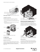
SafeZone™ Safety Laser Scanner User Manual 6.3.1 Restart interlock and external device monitoring Section 7 — Configuration +24V 7.1 Default delivery status k1 The SafeZone safety laser scanner is delivered in a safe default status. S1 • The device status is Waiting for configuration. k2 • Thus the switching outputs (OSSDs) are deactivated 442L-SFZNMZ (the red LED illuminates: ). • The 7-segment display indicates . . K1 K2 H8 H3 H2 0V 7.
SafeZone™ Safety Laser Scanner User Manual To configure the device, please read the user manual for the SCD software and use the online help function of the program. Display Meaning Section 8 — Commissioning 8.1 Initial commissioning ATTENTION l m m m m l l l l m Power-up cycle, step 2 m Power-up cycle, step 3 Device status Waiting for configuration or Object in the protective safety field, OSSDs l Commissioning requires a thorough check by qualified personnel.
SafeZone™ Safety Laser Scanner User Manual protective safety field shapes) and include these with the documentation. 8.2.2 Regular inspection of the protective device by qualified personnel Check the system following the inspection intervals specified in the national rules and regulations. This procedure ensures that any changes on the machine or manipulations of the protective device after the first commissioning are detected.
SafeZone™ Safety Laser Scanner User Manual l l m m m Other display Or: The device is operational, no object in protective safety field and warning field. IMPORTANT safety laser scanner is an optical part that must not be contaminated or scratched. The front screen is only allowed to be replaced by specialist personnel in a dust- and dirt-free environment. Never replace the front screen during operation as dust particles could enter the device.
SafeZone™ Safety Laser Scanner User Manual Insert the new seal —starting in the middle. During this process first align the center markings on the sensor head ( and ) and seal ( and ). ATTENTION The level of contamination is measured continuously during the operation of the SafeZone safety laser scanner. For this purpose the front screen calibration must first be performed; this then serves as a reference for the contamination measurement (status = not contaminated).
SafeZone™ Safety Laser Scanner User Manual If possible use anti-static floor mats and workbench covers. When working on the SafeZone safety laser scanner, touch a bare metal surface from time to time to discharge static charging of your body. Only remove the components for the SafeZone safety laser scanner from their anti-static packing immediately prior to installation. Note that no liability can be accepted for damage caused by electrostatic discharge.
SafeZone™ Safety Laser Scanner User Manual ² Clean the front screen. Application diagnostic output Front screen contaminated, still in 1 Hz operation At the Res_Req output Reset required ² The display goes off automatically when an input signal is present that corresponds to a configured monitoring case. ² Operate the control switch for restarting or resetting. 1 Hz If display Waiting for valid input signal does not go off: ² Check the cabling.
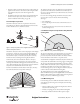
SafeZone™ Safety Laser Scanner User Manual ² Check the wiring and rectify the error. . . General OSSD wiring error ² Check the complete wiring of the OSSDs. . The SafeZone safety laser scanner is ² For the correct function of the safety laser scanner, always receiving no measured values within ensure that measured values are a range of at least 90° (measuring received within a range of 90°; range maximum 49 m), it thus is not this range can be moved as detecting any obstacles such as e.g.
SafeZone™ Safety Laser Scanner User Manual B = tB= Basic response time TMFA = Supplement due to multiple sampling > 2 d = Resolutions of the SafeZone safety laser scanner (mm) Basic response time for various resolutions The following basic response times apply for the internal OSSDs with standard multiple sampling of 2 without taking into account the switching time for the monitoring cases.
SafeZone™ Safety Laser Scanner User Manual 600 µ s OSSD1 300 µ s 300 µ s OSSD2 Figure 65: Voltage test after switching on the OSSDs 600 µ s OSSD1 300 µ s 300 µ s OSSD2 Figure 66: Figure 66: Shut-down test 600 µ s OSSD1 300 µ s OSSD2 300 µ s Figure 67: Voltage Test 44 10000073050, July 2011 Original instructions R
SafeZone™ Safety Laser Scanner User Manual 11.4 Data sheet Minimum Typical Maximum General Data Laser protection class Laser class I (21 CFR 1040, 10 and 1040.11, DIN EN 60825:2001) Enclosure rating IP65 (EN 60529) Protection class according to DIN VDE 0106, DIN EN 50178 II Type according to IEC/EN 61496, part 3 3 Functional safety programmable electronic system (IEC/EN 61508) SIL 2 PFD - probability of failure on demand (minimum requirement = 1E-2) 4.
SafeZone™ Safety Laser Scanner User Manual Minimum Typical Maximum Functional Data Protective safety field of the sensor head with 4.0 m scanning range at 120 ms response time At 30 mm resolution At 40 mm resolution At 50 mm resolution At 70 mm resolution At 150 mm resolution 2.80 m 3.80 m 4.00 m 4.00 m 4.00 m Protective safety field of the sensor head with 4.
SafeZone™ Safety Laser Scanner User Manual Minimum Typical Maximum Electrical Data Electrical connection Plug-in connection housing with screw terminal connections Technical data, screw terminals Cross-section of rigid cores 0.14 mm2 1.5 mm2 Cross-section of flexible cores 0.14 mm2 1.0 mm2 American Wire Gauge (AWG) 26 16 Insulation stripping length for the cores 5 mm Screw tightening torque 0.22 nm 0.
SafeZone™ Safety Laser Scanner User Manual Minimum Typical Maximum Static control input 2kΩ Input resistance when HIGH Voltage for HIGH 11V 24V 28.8V Voltage for LOW -3V 0V 5V Input capacitance 15 nF Static input current 6 mA 15 mA Input frequency (max. switching sequence or frequency) 1/(multiple sampling + 1) x scan time x 2 OSSDs Output signal switching device pair 2 PNP semiconductors, short-circuit protected, cross-circuit monitored HIGH switching voltage at 500 mA UV - 2.
SafeZone™ Safety Laser Scanner User Manual Minimum Typical Maximum Short-circuit current at TxD -60 mA 60 mA Max. voltage level at RxD -11V 11V Max. voltage level at TxD -11V 11V Data interface Communication protocol RS-422 (proprietary) Transmission speed (selectable) 19 200 baud 38 400 baud 125 kbaud 250 kbaud 500 kbaud Cable length at 500 kbaud and 0.
SafeZone™ Safety Laser Scanner User Manual 11.5 Dimensional drawings 11.5.1 SafeZone safety laser scanner 147 136.8 13.5 M8 x 9 Area to be kept clear during installation of the scanner 23 211 185 78.5 120 M6 x 8 55 27.8 65.2 155 Connector range approx. 270 93 63 53.2 35 31.7 Reference points for mounting Axis of rotation of motor 77.5 155 160 92.
SafeZone™ Safety Laser Scanner User Manual 11.5.2 Mounting kits 193.2 175 120 22.5 87.5 51.8 102 30 9 9 160 220 183 66.6 71 9 67 80 46 30 60 71 Figure 69: Dimensional drawing, mounting kit 1, 2 and 3 (mm) 11.5.
SafeZone™ Safety Laser Scanner User Manual Section 12 — Ordering Information The SafeZone multizone system is made up of the following components: 442L-SFZNSZ Scan head and I/O module — singlezone 442L-SFZNMZ Scan head and I/O module — multizone 442L-CSFZNMZ-X Prewired 13 conductor cable to SafeZone multizone memory module X is either 5 m, 10 m or 20 m 442L-ACRS232 RS232 configuration cable, two meters long or 442L-ACRS232-8 Eight meter RS232 configuration cable 12.
SafeZone™ Safety Laser Scanner User Manual 12.2 Accessories and replacement parts Table 30: Catalog numbers Description Catalog Number Mounting Kit 1: Mounting bracket for direct mounting at the rear on wall or machine. No adjustment facility. 442L-AMBSFZNMZ1 Mounting Kit 2: Bracket only in conjunction with mounting kit 1. Mounting at the rear on wall or machine. Longitudinal and cross-wise adjustment possible. 442L-AMBSFZNMZ2 Mounting Kit 3: Bracket only in conjunction with mounting kit 1 and 2.
SafeZone™ Safety Laser Scanner User Manual Section 13 — Annex 13.1 Manufacturer’s checklist Checklist for the manufacturer/installer for installing electro-sensitive protective equipment (ESPE) Details about the points listed below must be present at least during initial commissioning~they are, however, dependent on the respective application, the specifications of which are to be controlled by the manufacturer/installer.
SafeZone™ Safety Laser Scanner User Manual 13.2 Glossary AOPDDR Active opto-electronic protective device responsive to diffuse reflection (e.g. SafeZone safety laser scanner, see also IEC/ EN 61496-3) Control Input, static The monitoring cases are switched using the control inputs. The SafeZone safety laser scanner has one static control input.
SafeZone™ Safety Laser Scanner User Manual EC Declaration of Conformity The undersigned, representing the manufacturer and the authorised representative established within the Community Rockwell Automation, Inc.
SafeZone™ Safety Laser Scanner User Manual Catalogue number 445L-SFZNSZ 445L-SFZNMZ Series Description Safezone single-zone safety laser scanner Safezone multi-zone safety laser scanner If no series number is given, then all series are covered.
GuardShield is a trademark of Rockwell Automation, Inc. Guardmaster is a registered trademark of Rockwell Automation, Inc. www.rockwellautomation.com Power, Control and Information Solutions Headquarters Americas: Rockwell Automation, 1201 South Second Street, Milwaukee, WI 53204 USA, Tel: (1) 414.382.2000, Fax: (1) 414.382.