Safety Configuration & Diagnosis (SCD) User Manual R
Important User Information Because of the variety of uses for the products described in this publication, those responsible for the application and use of this control equipment must satisfy themselves that all necessary steps have been taken to assure that each application and use meets all performance and safety requirements, including any applicable laws, regulations, codes and standards.
Contents Contents 1 Product description. . . . . . . . . . . . . . . . . . . . . . . . . . . . . . . . . . . . . . . . . . . .2 2 User interface . . . . . . . . . . . . . . . . . . . . . . . . . . . . . . . . . . . . . . . . . . . . . . . . .3 User interface menu bar . . . . . . . . . . . . . . . . . . . . . . . . . . . . . . . . . . . . . . . . . . . . . . . . . . . . . 4 User interface toolbar . . . . . . . . . . . . . . . . . . . . . . . . . . . . . . . . . . . . . . . . . . . . . . . . . . . . . . .
Chapter 1 Product description Chapter 1 Product description Depending on purpose and operating mode, devices supplied by Rockwell may be configured differently. The SCD has a graphic user interface which allows you configure and diagnose devices supplied by Rockwell. The parameters of a configuration are transferred to the devices, where they are saved. Note The software is not suitable for the configuration and diagnostics of devices of other manufacturers.
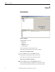
Chapter 2 User interface Chapter User interface Figure 1 - User Interface The user interface consists of: • Title bar (1) • Menu bar (2) • Toolbar (3) • Navigation area (4) • Log window (5) You can modify the size of the navigation area. The toolbar and the log window can be shown or hidden. How to show or hide the toolbars: From the View menu select the Toolbar command. If the toolbar was hidden before, it will now be shown. If the toolbar was shown before, it will now be hidden.
Chapter 2 User interface User interface menu bar Figure 2 - User interface menu bar The menu bar contains the commands for the fundamental operation of the software. Any further menus with device-specific commands are displayed in the menu bar. Notes Menus/commands that are shown in grey are currently not available (because the SCD is, for example, not connected to a device) or because you do not have sufficient access rights.
Chapter 2 User interface How to show or hide the toolbars: From the View menu select the Toolbar command. If the toolbar was hidden before, it will now be shown. If the toolbar was shown before, it will now be hidden. User interface navigation area Figure 4 - User interface navigation area The navigation area shows the devices in a device cluster hierarchically in a project tree.
Chapter 2 User interface Log window Figure 5 - Log window The log window displays a record of the executed actions, warnings and error messages when working with the SCD. The icons at the left-hand margin of the log window can be used to have information about the executed actions, warnings, errors and the time sequence of the program execution displayed. The log window can be shown or hidden.
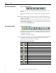
Chapter 2 User interface Table 5 - Icons in the project tree Icon Meaning of the icon Project/Communication protocol Physical connection (not connected) Physical connection (connected) Device icon, e.g. SAFEZONE The devices existing in the project tree can be displayed as “active” or “passive”: Table 6 - Icons in the project tree Icon examples Meaning Active devices are shown in color.
Chapter 2 User interface Project name Figure 7 - Project name You can change the name of a project. When the project is stored, the project name is suggested by the SCD as the file name. Use, for example, names as the project name with which you can allocate your projects to the machines or systems that are being backed up. How to change the name of a project: From the pop-up menu for the project, select the Change name... command. The Change project name dialog box opens.
Chapter 3 Device window Chapter 3 Device window Figure 8 - Device window (e.g. SAFEZONE) The device window is opened with a double-click on the device icon in the navigation area of the user interface. You can configure and diagnose the device in the device window. The device window consists of: • • • • • • • Title bar (1) Menu bar (2) Device information area (3) Toolbar (4) Navigation area (5) Working area (6) Status bar (7) The size ratio of the navigation and working windows can be changed.
Chapter 3 Device window Notes • • Device information area Menus/commands that are shown in grey are currently not available (because the SCD is, for example, not connected to a device) or because you do not have sufficient access rights. The explanation of the device-specific menus/commands can be found in the device-specific online help. This can be called up by using the table of contents of the online help (Contents button). Figure 10 - Device information area (e.g.
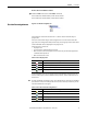
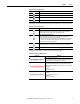
Chapter 3 Device window Table 8 - Icons in the device window toolbar Icon Meaning of the icon Show/hide device information Show/hide tree view Show/hide status bar Undo changes to the configuration Import device configuration Export device configuration Transfer configuration Receive configuration Page tab cards forwards Page tab cards backwards Call up context-sensitive help Device window navigation area Figure 12 - Device window navigation area The following elements are displayed in a tree structur
Chapter 3 Device window Table 9 - Icons in the device window navigation area Icon Meaning of the icon Navigation nodes (device, function of the SCD) Display Display that can be commented, blue arrow Tab card with configurable parameters Tab card being edited (edit configuration) The navigation area with the tree structure can be shown and hidden.
Chapter 3 Device window The icons at the upper margin of the working area can be used to save, print, update and comment the displayed reports. Note If some commands are shown in grey, the commands are currently not available (because the SCD is, for example, not connected to a device) or because you do not have sufficient access rights.
Chapter 4 Printer setup Chapter 4 Printer setup You can print the diagnostics reports and the configuration logs as hard copies. To this purpose a printer has to be selected and set up for the SCD. How to set up a printer for the SCD: From the Project menu select the Printer setup... command. The usual operating system dialog box for selecting and setting up the printer is opened.
Chapter 5 Validating products Chapter 5 Validating products For some devices you can validate additional functions in the SCD that have to be licensed. How to validate products in the SCD: From the Extras menu select the Validate products… command. The Validate products dialog box is opened. Select the product that you want to validate in the Product field. Enter the validation code in the Validation code field. Click the Validate button. The product is validated.
Chapter 6 Working with projects Chapter 6 Working with projects The devices which you configure, maintain or perform diagnostics with the SCD are managed in projects and shown in a project tree. The SCD allows you to: • • • Create projects and transfer them Use existing projects for further devices identical in the construction Create projects for configured devices/device clusters You can save the created or identified projects in files and open them again later.
Chapter 6 Working with projects How to connect the PC to a device from Rockwell (e.g. RK512 serial): Connect the 9-pin Sub D plug of the connecting cable to a serial interface of your PC. Remove the protective cap on the configuration socket of the device supplied by Rockwell. Connect the M8 x 4 plug to the configuration socket of the device and/or the device cluster. Notes • Ensure that the configuration line does not pass directly next to strong electrical drives or along power cables.
Chapter 6 Working with projects Select the folder in which you want to save the project. Enter a name for the project. Click the Save button. The project is now saved under the specified name and in the selected folder. How to save a project under another name or in another folder: From the Project menu select the Save as... command. A Windows directory dialog box is opened. Select the folder in which you want to save the project. Enter a name for the project. Click the Save button.
Chapter 6 Working with projects Select the project file to be opened. The project is shown in the SCD as a project tree; the name of the opened file is shown in the title bar. How to link a project to the connected devices: Note The SCD establishes a connection to all the connected devices below the level (project, communication protocol, physical connection) that is selected in the project tree. From the Project menu select the Connect command.
Chapter 6 Working with projects How to connect the PC to a device from Rockwell (e.g. RK512 serial): Connect the 9-pin Sub D plug of the connecting cable to a serial interface of your PC. Remove the protective cap on the configuration socket of the device supplied by Rockwell. Connect the M8 x 4 plug to the configuration socket of the device and/or the device cluster.
Chapter 6 Working with projects How to transfer the configuration to the devices: Notes • • You can transfer the configuration to the respective device/device cluster that is selected in the project tree. You can only transfer the configuration if you are logged in at a device or device cluster with machine maintenance personnel or authorized client rights. Use the right mouse button to open the pop-up menu of a device or system. There select the command Configuration draft, Transfer.
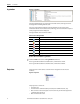
Chapter 6 Working with projects Figure 16 - Device selection wizard The class of devices you select there will depend on which device classes you have selected during installation. You can add devices directly to the project or cascading to a device. You can delete added devices from the project. How to add a device to a project: From the pop-up menu of the project select the Add device... command. The Device selection wizard dialog box is opened.
Chapter 6 Working with projects How to list the properties of a device: From the pop-up menu for the device, select the Properties command. The Device properties dialog box is opened. Here all data on the device that are related to the type code is listed.
Chapter 7 Configuring a device/device cluster Chapter 7 Configuring a device/device cluster The configuration of the devices is password-protected, with the effect that only the members of the appropriate user groups will be able to transfer configurations to the devices. Therefore change to the Machine operator user group if you leave the PC that is connected to the devices unattended.
Chapter 7 Configuring a device/device cluster If the opened configuration draft is changed, a red cross is displayed in the status bar. The configuration draft can no longer be transferred by a machine maintenance personnel user. A project with a verified configuration draft can be saved and later be opened and sent also to other devices by a machine maintenance personnel user.
Chapter 7 Configuring a device/device cluster Repeat the procedure for all the tab cards. Check all the contents of the tab cards whether the configuration data are suitable for your application. How to undo changes to the configuration: Select the Undo changes to the configuration command in the Device menu. You are prompted whether you want to reject all the changes to the configuration. Click the Yes button. All the changes to the configuration are rejected.
Chapter 7 Configuring a device/device cluster Here select the Open device window command. The device window is opened. Select the Import device configuration command from the File menu in the device window. A Windows directory dialog box is opened. Select here the device configuration file to be imported. Click the Open button. A message box is opened confirming that the device data have been imported. Click the OK button.
Chapter 7 Configuring a device/device cluster Click the Approve button. The configuration data are loaded to the device/devices and initialized with the new configuration. If this has been successful, an appropriate message is displayed. Click the OK button. The configuration loaded to the device/devices is now active. Test whether the device(s) actually monitor(s) your machine or system the way you intended. Only after completing this step, go to real-time operation.
Chapter 8 Changing the user group Chapter 8 Changing the user group There are various user groups in the devices from Rockwell: • Machine operator • Machine maintenance personnel • Authorized client These user groups have different levels of authorisation for editing and transferring configurations or for diagnosing the devices. Note The authorizations of the user groups are device-specific. The authorizations are explained in the device-specific online help.
Chapter 8 Changing the user group Click the Log on button. The dialog box is closed, the user group is authenticated and the new user group is displayed in the status bar. If the password was incorrect or some devices in a device cluster have a different password: The Device: enter password dialog box is opened so that you can enter the correct password.
Chapter 9 Changing the password Chapter 9 Changing the password The user group authorized client can enter/change the passwords for the user groups machine maintenance personnel and authorized client. The passwords are saved in the devices. This allows the devices to be protected from being configured by unauthorized persons. How to change the password: Using the right mouse button, open the pop-up menu of the device. Select the command Access rights, change password...
Chapter 10 Resetting the password Chapter 10 Resetting the password If you have forgotten the password for a device, you can reset the password. To do so, you need a so-called reset password. You will get this password once you have identified yourself in writing to the manufacturer. To do so, use the form Faxform.pdf on the SCD-CD-ROM. You will need the serial number of the device and the number of the device counter for identification. Both numbers can be found in the Reset password dialog box.
Chapter 11 Carrying out diagnosis Chapter 11 Carrying out diagnosis The SCD can be used to diagnose devices that are connected and linked to the SCD (or identified by the SCD). To this purpose the diagnostic data are loaded into the working area of the device window. You can print and save the diagnostic data. You can also insert a comment via an additional dialog box. This comment is also printed and saved.
Chapter 12 Entering comments Chapter 12 Entering comments You can add comments to the reports (configuration log and diagnostics report) that are displayed in the working area of the device window. These comments are also printed out and stored with the respective report. How to enter a comment: Click in the working area of the device window on the Comment icon The Comment dialog box is opened. . Enter the desired comment in the text field of the dialog box. Click the OK button.
Chapter 13 Chapter Annex 13 Annex List of tables Table 1: Icons in the user interface toolbar . . . . . . . . . . . . . . . . . . . . . . . . . . . . . . . . . . . 4 Table 2: Icons in the project tree . . . . . . . . . . . . . . . . . . . . . . . . . . . . . . . . . . . . . . . . . . . . . 5 Table 3: Icons in the user interface navigation area . . . . . . . . . . . . . . . . . . . . . . . . . . . 5 Table 4: Icons in the log window . . . . . . . . . . . . . . . . . . . . . . . . . . . . . . . . . . . .
Chapter 13 36 Annex Rockwell Automation Publication 10000455426 Ver 00 - January 2013
xx
www.rockwellautomation.com Power, Control and Information Solutions Headquarters Americas: Rockwell Automation, 1201 South Second Street, Milwaukee, WI 53204 USA, Tel: (1) 414.382.2000, Fax: (1) 414.382.