
Hardware Instruction Manual


SafeShield Safety Light Curtain Hardware User Manual
27
Table 14: Pin Assignment system connection M23 x 11 + FE
Notes
• For the connection of pin 9 and 10 only use cable with
twisted pairs, e.g. the Allen-Bradley Guardmaster
connection cables available as accessories (see
“Accessories” on page 45).
• If you do not use either a SafeShield function module to
improve the EMC behavior we recommend, especially
on cascaded systems, the termination of the
connections pin 9 and 10 (device communication) on the
system connection in the control cabinet using a resistor
of 182 W.
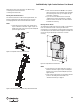
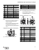
Configuration Connection M8 × 4 (Serial Interface)
Figure 28: Pin assignment configuration connection M8 × 4
Pin Wire Color Sender Receiver
1 Brown 24V DC input (voltage
supply)
24V DC input (voltage
supply)
2 Blue 0V DC (voltage supply) 0V DC (voltage supply)
3 Grey Test input:
0V: external test active
24V: external test inactive
OSSD1 (output signal
switching device 1)
4 Pink Reserved OSSD1 (output signal
switching device 2)
5 Red Reserved Reset/restart
6 Yellow Reserved External device
monitoring (EDM)
7 White Reserved Signal output (ADO)
8 Red/blue Reserved Output Reset required
9 Black Device communication A Device communication A
10 Purple Device communication B Device communication B
11 Grey/pink Input host/guest SEL Input host/guest SEL
FE Green Functional earthing Functional earthing
1
2
3
4
Table 15: Pin assignment configuration connection M8 × 4
Notes The pin assignment of sender and receiver is identical.
➢ After configuration always remove the connecting cable
from the configuration connection!
➢ After the configuration of the device has been
completed, locate the attached protection cap to cover
the configuration connection.
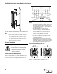
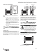
Extension Connection M23 × 11 + FE
Figure 29: Pin assignment extension connection M23 × 11 + FE
Table 16: Pin assignment extension connection M23 × 11 + FE
Pin Sender/ Receiver PC-Side RS-232-D-Sub
1Not assigned
2 RxD Pin 3
3 0V DC (voltage supply) Pin 5
4 TxD Pin 2
Pin Wire Color Sender Receiver
1 Brown 24V DC output (voltage
supply)
24V DC output (voltage
supply)
2 Blue 0V DC (voltage supply) 0V DC (voltage supply)
3 Grey Reserved Input emergency stop/
switch for deactivating the
blanking
4 Pink Reserved Input emergency stop/
teach-in
5 Red Reserved Reset/restart
6 Yellow Reserved Test output emergency
stop/teach-in
7 White Reserved Test output emergency
stop/switch for
deactivating the blanking
8 Red/blue Reserved Output Reset required
9 Black Device communication A Device communication A
10 Purple Device communication B Device communication B
11 Grey/pink Output host/guest SEL Output host/guest SEL
FE Green Functional earthing Functional earthing
51067118
432
FE
91
1067
3
118
4291
FE
5