
User Manual

Publication GMSI00-UM001A-EN-E - February 2005
Setting Up Measurements 59
Typical voltage measurement definitions
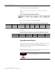
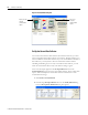
Figure 3.13 shows the setup for three typical voltage measurement definitions.
Figure 3.13 Voltage measurement definitions
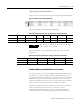
The following table shows the collection specifications.
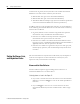
The following table shows the transducer specifications in the collection
specifications.
Combining Measurement Definitions for a Location
You can use Emonitor to set up many different measurement definitions for
data collection at a location. These can include magnitude, spectrum, time
waveform, and numeric measurements. You can then select the measurement
definitions you want to load to the data collector by creating a list of those
measurement definitions. When you want to load the data collector, Emonitor
builds a load file containing the measurement definitions in the list.
Emonitor combines measurement definitions at each location to make data
collection more efficient. This allows you to collect two or more
measurements automatically, without having to start each measurement
separately. The rules for combining measurement definitions depend on
Table 3.17 Collection specifications for voltage measurement definition
Transducer Window Signal Detection Fmax Lines Phase Order Norm? Averages
Voltage Hanning RMS 2 kHz 400 No No 4 linear
Voltage DC Rectangular None 2 kHz 400 No No 4 linear
TIP
The "Voltage" transducer is for Volts AC. The "Voltage
DC" transducer is for Volts DC.
Table 3.18 Transducer specifications in voltage collection specification
Name Base Unit Input Type Units Calibration Value DC Offset
Voltage Voltage AC Coupled V 1000 0
Voltage DC Voltage DC Coupled Vdc 1000 0