
User Manual

Publication GMSI00-UM001A-EN-E - February 2005
50 Setting Up Measurements
7. Move down to the next empty row in the measurement definition
spreadsheet, and select Edit > Paste to paste the copied measurement
definition.
8. Edit the new measurement definition by changing the measurement
filter. Select a band filter centered on the next order.
9. Repeat steps 6 and 7 to create measurement definitions for the desired
orders. You can then include these measurement definitions in a list and
load it to the data collector. Remember that you must have a trigger
signal to collect magnitude and phase at an order.
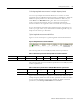
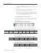
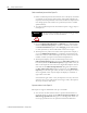
Typical magnitude and phase measurement definitions
The Measurement Definition pane for one through four orders might look like
Figure 3.9. Note that all measurement definitions have the same units and
collection specification.
Figure 3.9 Magnitude and phase measurement definitions
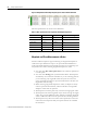
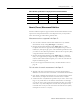
The following table shows the collection specification for Mag & Phase.
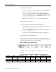
The transducer specification in the Mag & Phase collection specification is
shown in the table below.
The filter specifications are shown in the table below:
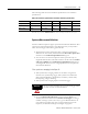
Table 3.8 Collection specification for mag & phase measurement definitions
Transducer Window Signal Detection Fmax Lines Phase Order Norm? Averages
Accelerometer Hanning Peak 500 Hz 400 Yes Yes 4 linear
Table 3.9 Transducer specification in mag & phase collection specification
Name Base Unit Input Type Units Calibration Value DC Offset
Accelerometer Acceleration ICP Accel g’s 100 0
Table 3.10 Filter specifications in mag & phase measurement definitions
Name Low Cutoff High Cutoff Data collector filter type
1st Order 0.8 Orders 1.2 Orders None